buckeye2019
Active Member
- Joined
- Nov 18, 2021
- Messages
- 33
- Reaction score
- 6
- Points
- 8
- Age
- 56
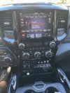
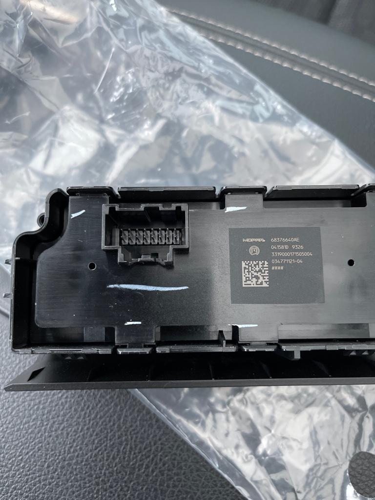
This is my switch bank I found on eBay. I have been in contact with 4wheelelecteonics.com and they are almost ready to release the switch bank box to make all the aux switches work. Here are the pics of my switches. The black is my old uplifter switches the other one is the switches I bought off eBay.