SilverSurfer15
Ram Guru
- Joined
- Jan 21, 2019
- Messages
- 1,129
- Reaction score
- 724
- Points
- 113
- Age
- 39
I just installed mine today. Cutting those threads that are painted is the worst part. My driver side was terrible, to the point the die is about dead but it worked. (eBay special lol)
The actual install isn’t too bad. The “gotcha” moments:
1) I had to trim the “ear” off the driver side motor cover piece. Just a small section but there’s no way that motor was going on in the correct orentination without cutting the corner off. Passenger side was fine. Unsure if I did something wrong but I don’t think so. Same part numbers on the motors so ???
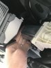
2) wiring is mostly easy. Getting the wires through the dash..... the gromet is to the right of the steering colum, not below (from the engine bay). Which was consuming to me at first. Pro tip, start from the inside. Punch a hole with a razor, stick your finger through it and create some actual work space. Then go back up to the engine bay, tie the wire ends back and together and cram in through said hole.
3) I felt the same way about the dash piece on left. So I didn’t take it off. You don’t have to. Now if you have huge hands or arms it might suck. But I did it, just have to get in the right position. For me that was laying with my head towards the foot rest (far left inside) and reaching up with my left hand in there basically directly under it to get like 50% in, then went back to laying 90 degrees different, head toward the center console which is probably how you started. Then reach up with right hand and actually plug it in. Might sound dumb, but when you try it you will see. You might be able to plug it in from the second spot all in one go but I could twist the damn plug in the correct orientation and get it in from there.
4) I could not drill through the pinch weld. I broke one bit, went and bought some new Milwaukee. Couldn’t do it. Got like 50% and the bit was just sliding down vs going in further. I’ve drilled many a holes") but that one wasn’t happening. Not sure if I picked a bad spot or what. So I said F that, filled it with RTV silicone. Might paint it? We will see how it dries. That’s all I had and thought it might work ok.
but that one wasn’t happening. Not sure if I picked a bad spot or what. So I said F that, filled it with RTV silicone. Might paint it? We will see how it dries. That’s all I had and thought it might work ok.
I just mounted them to the frame. It doesn’t work as good as the body mount, but it’s good enough for me. I might see about drilling the holes again later and put some new adhesive on them. Curious if anyone else had a problem drilling the pinch? I figured it would be simple. I even dropped to a smaller one, went up to a bigger one. Couldn’t get anything. Like it was hitting something HARD.
Overall not too bad. Actual amount of time I spent though was probably 7 hours. A lot of that was shrink wrapping and routing the wiring and what not.
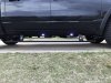
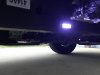
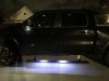
This is how I did the lights if anyone cares. I moved the rear one forward, a bit too far I think in hindsight. But I wanted it to be more where you would step out and not closer to the back, but I should have gone back another 2”. And a view from the backseat, getting out, the light output is still pretty good. Just too far forward.
The actual install isn’t too bad. The “gotcha” moments:
1) I had to trim the “ear” off the driver side motor cover piece. Just a small section but there’s no way that motor was going on in the correct orentination without cutting the corner off. Passenger side was fine. Unsure if I did something wrong but I don’t think so. Same part numbers on the motors so ???
2) wiring is mostly easy. Getting the wires through the dash..... the gromet is to the right of the steering colum, not below (from the engine bay). Which was consuming to me at first. Pro tip, start from the inside. Punch a hole with a razor, stick your finger through it and create some actual work space. Then go back up to the engine bay, tie the wire ends back and together and cram in through said hole.
3) I felt the same way about the dash piece on left. So I didn’t take it off. You don’t have to. Now if you have huge hands or arms it might suck. But I did it, just have to get in the right position. For me that was laying with my head towards the foot rest (far left inside) and reaching up with my left hand in there basically directly under it to get like 50% in, then went back to laying 90 degrees different, head toward the center console which is probably how you started. Then reach up with right hand and actually plug it in. Might sound dumb, but when you try it you will see. You might be able to plug it in from the second spot all in one go but I could twist the damn plug in the correct orientation and get it in from there.
4) I could not drill through the pinch weld. I broke one bit, went and bought some new Milwaukee. Couldn’t do it. Got like 50% and the bit was just sliding down vs going in further. I’ve drilled many a holes
but that one wasn’t happening. Not sure if I picked a bad spot or what. So I said F that, filled it with RTV silicone. Might paint it? We will see how it dries. That’s all I had and thought it might work ok. I just mounted them to the frame. It doesn’t work as good as the body mount, but it’s good enough for me. I might see about drilling the holes again later and put some new adhesive on them. Curious if anyone else had a problem drilling the pinch? I figured it would be simple. I even dropped to a smaller one, went up to a bigger one. Couldn’t get anything. Like it was hitting something HARD.
Overall not too bad. Actual amount of time I spent though was probably 7 hours. A lot of that was shrink wrapping and routing the wiring and what not.
This is how I did the lights if anyone cares. I moved the rear one forward, a bit too far I think in hindsight. But I wanted it to be more where you would step out and not closer to the back, but I should have gone back another 2”. And a view from the backseat, getting out, the light output is still pretty good. Just too far forward.
Attachments

Last edited:


 This technology has been employed by BMW, Mercedes, and Audi in their top models for some time. I believe our RAMs are the first in the light truck segment to employ this design. The frame must be very strong and rigid for this to work. The primary function of the ATTM is to cancel vibrations of the Hemi when in 4 cylinder mode by creating vibrations 180 degrees out of phase. Technically this is called "destructive interference."