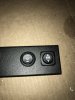
Yea I think you are missing the point of the switch. The switch is to override the auto deploy or retract function.
Examples:
Down: I want to clean the truck and put both steps down permanently while I do so and not have them moving up and down constantly as I’m in and out of the vehicle. I flip switch down, they drop and hold. I get in and out as many times as I want without the steps moving.
Up: I’m stuck in some muddy area, I want to open the door and get out but I don’t want my step to deploy down into the mud. (Or whatever it is). I flip switch up, now I can open and close doors as I wish without them going down.
The 30 min thing is just how long the “override” lasts. After 30 mins, the step will return to its default behavior upon the next door cycle. So if they are down they won’t retract after 30 mins. Just on the next door cycle after 30 mins has passed.
They have always worked on the pressure resistance since the very beginning of the product. But it’s annoying to have to go around to both sides and drop the steps to prevent door dings. And even that doesn’t help with the scenarios I mentioned above. There’s no way to stop it from moving other than unplugging the OBD. and even that’s not an option on the original ones that you had to tap the door ajar wire.