I finished installed the AMP Research power steps today on my 2019 Ram 1500 Laramie, along with the manual override switch. I started at 9:30 and finished at 2:30, which included two trips to the parts store for a few things (a step-bit to install the switch, and a M8x1.25 thread die). Overall, I'd guess it took me, working by myself, 4 solid hours of work. Knowing what I know now, I think it could be done in 3 - 3.5 if you had all your tools out and ready to go from the beginning, instead of getting up and down 9000 times to get something I needed under the truck. :-/
I only ran into two real issues - the first was what I posted earlier this morning, trying to move the harness on the drivers side. The fix that was suggested worked great, and is a lot easier than trying to hunt down a position for the wire harness to make it work. The other was installing the override switch - they terminate one end with long pins to fit into the controller block. One of the pins snapped off somehow when I was inserting it - I certainly wasn't putting any pressure on it. Maybe it was weak, I don't know, but there it is. I'll chat with AMP on Monday, but I expect it'll be a minor pain to fix it.
A few tips I found:
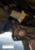
1. I fished the wiring through the rubber gasket next to the steering control. I used a wire coat hangar, taped the ends of the wires into a loop, bent the end of the hangar into a hook, and pulled it back through. Easy peasy. MAKE SURE YOU SUPPORT THE GASKET WHEN YOU PULL BACK THROUGH. It doesn't seem like it's in there very tightly, I could imagine ripping it out pretty easily.
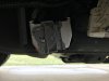
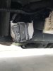
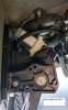
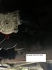
2. I mounted the LED's to the frame behind the steps, instead of through the pinch weld, just based on what I saw earlier in this thread. Seems fine to me and less drilling == better IMO.
3. For the step/motor mounts on the passenger/driver side, make sure you screw the nut underneath the gears before you tighten everything down. There's not a lot of room there and if you tighten the others before screwing on the nut, you'll be pulling it back off.
4. When you mount the motor on the passenger side, loosen ALL of the nuts on the step mount until they are nearly off the studs. That was the only way I could get enough clearance to tighten/torque the top screw of the motor to the mount. Then tighten the step mount back up.
That's pretty much it. It's a bit time consuming, but really not a difficult install.
Here's a few pics, including where I decided to mount the override switch. It's out of the way which I like and there was plenty of open space behind the panel there. It's not a removable panel, but I didn't really care that much about that.
View attachment 17680View attachment 17681View attachment 17682View attachment 17683