5thGenRams Forums

Register a free account today to become a member! Once signed in, you'll be able to participate on this site by adding your own topics and posts, as well as connect with other members through your own private inbox!

Is it possible to add Blind Spot?

tdb0021

Well-Known Member
Joined
Mar 17, 2020
Messages
231
Reaction score
199
Location
Denver, CO
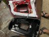
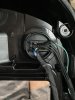
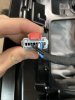
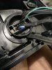
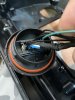
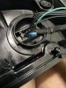
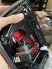
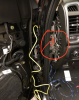
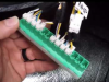
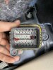
So to chime in here, thanks to everyone who is looking at this thread. I was the original poster and was very pleased when I saw that some work has been done on this effort. On my end, I do have LED's so looking at the pics, I would like to see if it's possible to "just" add the blind spot module by carving out a void in my LED's to accomodate the monitor and then wiring it up. The tricky part is the wiring. If one looks at the back on the non- blind LED lights, one can clearly see the only difference is that the back is sealed but the holes for the screws to mount the BS monitor are there and you would need to then add wires to the male harness because if you look closely, you can see the non- blind LED version has the bottom 5 pins missing. I looked at the male harness on the Monitor itself and it has 7 male pins- see last pic. Any thoughts? Has anyone done this? It's cheaper than buying the whole unit but I am not sure it would be worth the savings to get the wiring to work.

Do you have the LED tail light with the BSM? If we can figure out the pin locations for the wires it should be a simple process to add wires to the non bsm tail light. This is assuming you can pull the wiring harness out of the tail light itself.
 

tdb0021

Well-Known Member
Joined
Mar 17, 2020
Messages
231
Reaction score
199
Location
Denver, CO
Okay, I’ve made some headway on this. I got a factory bsm tail light that I took apart to get the wiring info. See the picture for the pin locations. The 5 wires (3 black, 1 white, 1 blue) are the ones we need to add to a non factory bsm tail light.

C4E0D8FA-2E56-4FC2-92F3-DE590CF33538.jpeg

I also need to determine what the part number is for the grey connector so I can make the harness, if anyone knows this that’d be helpful.

EEA3E3E1-5DB9-4171-BDB1-E9981B5D49B8.jpeg

There are 2 ways to get the connector out from the tail light. The risky way is to remove the tail light lens and 4 screws holding the internals together (the risk being breaking the cover or losing a watertight seal when you put it back together). The other way is to reach into the opening (you would have to cut this opening first on a non bsm tail light) and push the small plastic “pin” up and rotate the connector counter clockwise. This will release the connector enough to add the wires. See pictures for details.
 

Attachments

  • 8B130287-B8E2-443B-99F5-92A261C11A8F.jpeg
    8B130287-B8E2-443B-99F5-92A261C11A8F.jpeg
    224.3 KB · Views: 379
  • 1CF2AE36-66B8-4D22-8913-FAB04E2BCBC4.jpeg
    1CF2AE36-66B8-4D22-8913-FAB04E2BCBC4.jpeg
    109 KB · Views: 363
  • 7DFE81E4-6D8E-461D-81FE-50AFAE2BE7DD.jpeg
    7DFE81E4-6D8E-461D-81FE-50AFAE2BE7DD.jpeg
    88.1 KB · Views: 358
  • A3DE47D6-547C-47AD-A5A1-C144867ADA7A.jpeg
    A3DE47D6-547C-47AD-A5A1-C144867ADA7A.jpeg
    136.7 KB · Views: 356
  • EB32F7B6-35D2-4B31-9765-8282F6BA7C88.jpeg
    EB32F7B6-35D2-4B31-9765-8282F6BA7C88.jpeg
    109.9 KB · Views: 353
  • A1FEF3D1-7805-4D48-A2C8-3B257589597F.jpeg
    A1FEF3D1-7805-4D48-A2C8-3B257589597F.jpeg
    139.7 KB · Views: 364
  • 100FDF18-FFF8-40CA-896B-2DE6A3C3B2B6.jpeg
    100FDF18-FFF8-40CA-896B-2DE6A3C3B2B6.jpeg
    154.9 KB · Views: 375

mike_ct

Ram Guru
Joined
Nov 21, 2018
Messages
645
Reaction score
413
Okay, I’ve made some headway on this. I got a factory bsm tail light that I took apart to get the wiring info. See the picture for the pin locations. The 5 wires (3 black, 1 white, 1 blue) are the ones we need to add to a non factory bsm tail light.

View attachment 54856

I also need to determine what the part number is for the grey connector so I can make the harness, if anyone knows this that’d be helpful.

View attachment 54857

There are 2 ways to get the connector out from the tail light. The risky way is to remove the tail light lens and 4 screws holding the internals together (the risk being breaking the cover or losing a watertight seal when you put it back together). The other way is to reach into the opening (you would have to cut this opening first on a non bsm tail light) and push the small plastic “pin” up and rotate the connector counter clockwise. This will release the connector enough to add the wires. See pictures for details.
Fantastic contribution! I’ll start searching for that bsm connector.
 

mike_ct

Ram Guru
Joined
Nov 21, 2018
Messages
645
Reaction score
413
Last edited:

tdb0021

Well-Known Member
Joined
Mar 17, 2020
Messages
231
Reaction score
199
Location
Denver, CO

tdb0021

Well-Known Member
Joined
Mar 17, 2020
Messages
231
Reaction score
199
Location
Denver, CO
I think i'm close to figuring out the wiring from the driver seat to the CAN Bus. I found a helpful website that has a lot of free wiring info for our truck. You can find all the connectors and pin outs from the diagram on this website:
http://connectors.dcctools.com/home.htm

using this and the diagram for the blind spot system from tech authority i think we have the info, i'm just having trouble decoding it all. Anyone able to offer some advice on reading this? It looks like all i need to know is where exactly to plug the wires into at the CAN Bus.


IMG_2991.jpg
 

mike_ct

Ram Guru
Joined
Nov 21, 2018
Messages
645
Reaction score
413
did you access the can bus hub's yet ? if you pull the side cover off the driver side dash, they are clipped in behind the metal plate you'll see. green one and white one. they have a bunch of the same connectors plugged in, with thin twisted pair wires. they call it the star connector. I've spliced to existing wires leaving the connector before (I did this when I created my own bypass, and added my own 2nd obd2 port) but really, we should find the connectors for the star connector and plug them in properly.
 

Attachments

  • Screen Shot 2020-05-07 at 12.55.18 PM.png
    Screen Shot 2020-05-07 at 12.55.18 PM.png
    1.1 MB · Views: 299
  • Screen Shot 2020-05-07 at 12.58.07 PM.png
    Screen Shot 2020-05-07 at 12.58.07 PM.png
    417.7 KB · Views: 295

tdb0021

Well-Known Member
Joined
Mar 17, 2020
Messages
231
Reaction score
199
Location
Denver, CO
i bought the correct connector for this pn# A124362CT-ND and A128871-ND from a website. so what i'm gathering is it doesn't matter where it's plugged in at the canbus? just as long as it's plugged in?
 

mike_ct

Ram Guru
Joined
Nov 21, 2018
Messages
645
Reaction score
413
i bought the correct connector for this pn# A124362CT-ND and A128871-ND from a website. so what i'm gathering is it doesn't matter where it's plugged in at the canbus? just as long as it's plugged in?
correct, it can plug into any empty port on the star connector.
from a technical standpoint, I wonder how the bcm figures out which one is left and which one is right, since the BSM sensors are same part numbers for both tail lights?
 

tdb0021

Well-Known Member
Joined
Mar 17, 2020
Messages
231
Reaction score
199
Location
Denver, CO
Good question. Each sensor is a 5 pin, but there are only 4 wires that need extending to the canbus. I bet those other wires are at play in determining which is left vs right.

Just to update: I was able to find the connector under the driver seat. Problem is i don't know how to add the pins to it. It's double sealed. I imagine the process is difficult. I ended up cutting the wires off from where they go up through the floor to extend them. Drilled a small hole next to the connector and ran them through it and sealed it all up. I think this is the best way to do it without re-pinning the plug. Now i'm waiting on my other sensor to be delivered so i can add them to my taillights.
Also, that $1.71 connector works if you modify it. I tried it out yesterday. IMG_2996.jpg

IMG_2994.jpg
IMG_2997.jpg
 

Attachments

  • IMG_2995.jpg
    IMG_2995.jpg
    173.8 KB · Views: 225

mike_ct

Ram Guru
Joined
Nov 21, 2018
Messages
645
Reaction score
413
yes! i saw the $1.71 connector was key A, and i think we technically are a key B, so one one the slots or tabs looks like it needed trim. and i was going to do the same thing - just cut the wire under the cab, and bring it thru a new hole, and not bother trying to pin the connector or take the seat out, etc.

nice job!!!
 

tdb0021

Well-Known Member
Joined
Mar 17, 2020
Messages
231
Reaction score
199
Location
Denver, CO
Ok so I made a interesting discovery today. It looks like on my truck the wiring that the taillight plugs into for bsm is not present. Not sure what to make of this. 38FF6753-3162-48DD-B6CB-B20773AAB402.jpeg
 

mike_ct

Ram Guru
Joined
Nov 21, 2018
Messages
645
Reaction score
413
Turns out this short wiring harness needs to be replaced with the correct bsm one. part numbers 68357220AC (driver) & 68357222AC (passenger). about $22 each.
thats what they call the "jumper" harness, right?
are you going to buy them? or just run your own wires. I think the jumper is only like 24" long. If you've gone this far, you can probably just pull them out from the other end of the jumper plugs in and get them to the tail lights. I bet the colors are the same.
 

tdb0021

Well-Known Member
Joined
Mar 17, 2020
Messages
231
Reaction score
199
Location
Denver, CO
thats what they call the "jumper" harness, right?
are you going to buy them? or just run your own wires. I think the jumper is only like 24" long. If you've gone this far, you can probably just pull them out from the other end of the jumper plugs in and get them to the tail lights. I bet the colors are the same.

yes these are the “jumpers”. I went ahead and ordered them. You could easily find the correct pin part no. and repin it, but I have to wait on other parts so I went ahead and ordered the jumpers.

In other news, I was able to successfully add a bsm sensor to my stock tail light. I dremeled out the hole and was able to get the wire harness in. It all worked great. I recommend using silicone or another sealant around the metal sensor bracket just in case it doesn’t seal properly with the gasket. I still have to do the other one, I think i might make a small how-to video. Getting that connector to twist out will be hard if you don’t know exactly what to look for.
 

mike_ct

Ram Guru
Joined
Nov 21, 2018
Messages
645
Reaction score
413
yes these are the “jumpers”. I went ahead and ordered them. You could easily find the correct pin part no. and repin it, but I have to wait on other parts so I went ahead and ordered the jumpers.

In other news, I was able to successfully add a bsm sensor to my stock tail light. I dremeled out the hole and was able to get the wire harness in. It all worked great. I recommend using silicone or another sealant around the metal sensor bracket just in case it doesn’t seal properly with the gasket. I still have to do the other one, I think i might make a small how-to video. Getting that connector to twist out will be hard if you don’t know exactly what to look for.
I saw your picture earlier, that connector looks like an odd fit. I have a left sensor with the aluminum backer, but the right side I have sensor only, I have to find a right side aluminum backer.
 

tdb0021

Well-Known Member
Joined
Mar 17, 2020
Messages
231
Reaction score
199
Location
Denver, CO
I saw your picture earlier, that connector looks like an odd fit. I have a left sensor with the aluminum backer, but the right side I have sensor only, I have to find a right side aluminum backer.

I got lucky and found a sensor and aluminum backer on eBay for 65$ shipped... hopefully it works! The last 2 things I’m waiting for is the metal pins for the wiring for my other tail light and the jumpers. Once I have those two items I’ll be able to enable everything in AlfaObd. I still have to install the side mirrors (Which I have) but I’m waiting on my passive entry parts to be in so I can knock it all out at once.
 

tdb0021

Well-Known Member
Joined
Mar 17, 2020
Messages
231
Reaction score
199
Location
Denver, CO
I cleaned up the wiring from the driver seat to the CAN IHS today. The connector is PN: A128871-ND and pins are PN: A124362CT-ND. Only 2 connectors and 4 pins are needed, but i picked up extras incase i messed something up. These plug in to the CAN IHS right next to where the left driver foot rests. You need to remove the plastic trim piece to get to it. Waiting on a few more parts before i can complete the rest.

IMG_3007.jpg

IMG_3008.jpg
 

tdb0021

Well-Known Member
Joined
Mar 17, 2020
Messages
231
Reaction score
199
Location
Denver, CO
I did a write up for all those who will eventually have questions on how to do this. Hopefully these instructions are clear. I still haven't completed the install, so if something changes i'll update accordingly.
 

Attachments

  • Adding Blind Spot Monitoring.pdf
    1.1 MB · Views: 619

Users who are viewing this thread

Top