5thGenRams Forums

Register a free account today to become a member! Once signed in, you'll be able to participate on this site by adding your own topics and posts, as well as connect with other members through your own private inbox!

How To: Adding OEM Upfitter Aux Switches on 2019+ Ram 1500 (DT)

suli

Active Member
Joined
Apr 22, 2020
Messages
43
Reaction score
22
Points
8
Age
48
Location
World

Upfitter Aux Swithes on 2019+ Ram 1500 (DT) - How-to

Will be adding content, part numbers, updates etc as needed, majority of the content is now updated in this thread.

IMPORTANT CAVEATS:​

====================================================================================
* MODIFY YOUR VEHICLE AT YOUR OWN RISK! *
* ZERO RESPONSIBILITY OF ME, FORUM MEMBERS HERE, MEMBERS OF OTHER FORUMS, OR FROM THE INTERNET FOR ANYTHING YOU BREAK AND/OR GOES WRONG AND/OR BAD PARTS. *


PREFACE:

====================================================================================
First, huge thanks to the community here and the following threads and if you'd like to do some of your own research, this has been five years in the making:
Also, over at HDRams.com here:
Specifically to:
@kc9umr (for the Aux Switches p/n's image matrix)
@Jimmy07 (for the aux switches connector view and pins)
@Abhi.K (for the BCM swap details, connector part numbers, and willing to help)
(sorry if I missed anyone!)

NOTE:

If you have a 2021+, you likely will not need a programmed or new BCM, just activate the switches in the BCM with something like jScan or AlphaOBD with the new Aux panel plugged in.
You'll still need to plug into the harness/aux panel and into a fuse/relay box, buy or make one with details below

NOTE2:

You may be able to find the correct Upfitter Auxiliary Switch Kit from Mopar that comes with the Aux Switch, Relay Box, and side power connectors for plugging into it (power cable only, OEM style).
I'm not sure anyone has figured out the matrix of Kit numbers to Aux panels for people to order the right one if you want 100% Factory OEM upfitter.


Process:​

====================================================================================
1. Install a new AND dealer programed BCM if you your model year requires it (or get your current BCM flashed by @Jimmy07)
1a. Install a required updated shifter if you upgraded and swapped your BCM
2. Install the upfitter Aux switch panel
3. Program the BCM to use the Aux swicthes (dealer is the LHL sales code) with Jscan or AlphaOBD
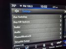
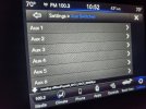
4. Verify buttons work and if supported, also shows up in your settings menu in uConnect
5. Install AUX wires to AUX panel connector and run to engine bay.
6. Install Fuse/Relay/PDU/BDU in eninge bay
7. Install Aux leads to fuse/relay box
8. Install Aux out lines from relay box to your connector of choice
9. Test with a small led bulb


Stuff You'll Need to add the OEM Aux Switches:​

====================================================================================
1. Correct Body Control Module and have it programed by your dealer (for 19-20)
- Suggested p/n: 68584071AG for a '23
- Any BCM 22+ will work, suggest a 2023+ due to if you want to eventually do uConnect v5
- If you have a 21+, you may not need a new BCM, try it first!

1a. (Option) Program your BCM to a 2022 versioned BCM to get a "correct" BCM to use
- Ping @Jimmy07 and he can assist.
-- Will require sending away your BCM, so you won't be able to drive your truck until it comes back.
- Only drawbacks are downtime and lack of uConnect5 upgrade option.

2. Dial Shifter when updating BCM
- Suggested p/n: (depends on what you have)
- Example, my 19' has 4wd, and auto-off, so I needed p/n: 68503750AC
- If you dont need the BCM update, you wont need a new shifter.

3. Aux Switches
- Suggested p/n: (depends on what you have)
- Example, my 19' has park sesnse front, park sense rear, tow/haul, traction, so I got a non-glossy version of 68578990AA, glossy version is 68476024AB (old rev 68376640AA)

4. Harness Adapter and under hood Power Distribution Unit
- You have two options here: Make it or Buy it
-- Buy it
--- If you want to just buy it, 2013-Current Ram Auxiliary Relay Assembly (without dash button panel) | Mysite
--- Be mindful of their fuse/wire size spec on this prebuilt unit, may not fit what your needs are for power, check and verify for your use.
-- Make it
--- You need to build an adapter that plugs into the back of the AUX panel and a relay/power distribution box
--- If you want to make this, continue in this thread below

5a. OBD2 Adapter
- The Vgate works well and can be updated: Vgate vLinker MC+ Bluetooth OBD2 Car Diagnostic Scan Tool for iOS, Android & Windows
-- Amazon.com

5b. Mopar Specialized Programmer
- JScan is my goto Mopar programer
-- JScan – OBD JScan – Mobile Jeep, Chrysler, Dodge Diagnostic Tool or you app store
- People also like using AlphaOBD
-- AlfaOBD or your app store

5c. Security Bypass cable
- Programmers may need a different cable, use what they suggest
-- JScan has a list here: JL/JT FCA Security Gateway Module – JScan
-- I use this one: Amazon.com

6. Black sealing heat shrink tubing various sizes - helps seal connectors and keep tape and loom tidy.


Optional Items​

====================================================================================
7. Dialectic Grease - Comes in handy for electrical connectors, esp under the hood and apply to connectors
8. Clear Shrink Tube - if you label your cables with printed or hand written wire labels
-- Amazon.com
9. Fabric Electrical Tape - for that sweet OEM look to wrapped cable bundles
-- Just look for "Wire Harness Automotive Cloth Tape"
10. Flex Loom/ Mesh loom for wrapping cables under the hood for abrasion resistance and OEM look
-- Amazon.com (1/4")
-- Amazon.com (1/2")
-- Amazon.com (3/4")
-- Amazon.com (3/8")
-- This looks like neat stuff, wire loom but heat shrink too?? Wow Amazon.com (3/8" but they have diff sizes)
11. Black Silicone Sealant (find a squeeze tube) to extra seal where you pull wires through the firewall
12. High Quality Zip ties
13. Under hood PDU bracket such as
-- Mounting Kit for Auxbeam Switch Panel | 5th Gen | 2019 - 2024 RAM 1500 DT & Rebel
-- RELAY BOX MOUNT
-- Fuse-Relay-Breaker Mounting Kit - RAM1500 DT


Tools​

===================================================================================
- Standard set of shop and trim tools
- Some plug pin removal tools are helpful to pull pins from connectors
- Quality electrical crimping tool for connectors you purchase, may vary
- Heat gun for shrink tubing
- Bonus: Tape labeler or labels for hand writing labeling (and clear shrink tubing noted above for your labels on cables)
- Bonus: Soldering iron/station setup if you solder your connectors too
 
Last edited:

What Aux Switch Bank Module to Buy?​

===================================================================================

Great, you have a BCM that support the Aux buttons now from either having a '21+ or upgraded your BCM in your truck. Now, how to figure out what switch part number to get?
(Please if you have other numbers (more than revision PNs like AC, AD, etc), please reply or DM me, I'll add them to the list)

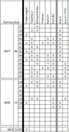
This image is a handy chart for the AUX switch panels based on what YOU CURRENTLY HAVE IN YOUR TRUCK.

switches.JPG

P/N(Finish)Tow/HaulTraction ControlPark Sense FrontPark Sense RearTrailer Height/Air Lower
68476018ABGlossxx
68578987AAMattexx
68476044ABGlossxxx
68579000AAMattexxx
68578990AAMattexxxx
68476024ABGlossxxxx
68578990AAMattexxxx
68376640AEGlossxxxx
68476025ABGlossxxxxx
68578991AAMatexxxxx


Example:
My 2019 has the following buttons from the factory: park sense front, park sense rear, tow/haul, traction control.
Looking at the chart, hmmm, that isn't listed for only 6 AUX but shows a 5 AUX with PTO as 68376640AA, not what I need. But wait! There's reportedly another version release, and it's 68476024AB. Hold on, there's another version with the same buttons, a non-glossy top button row is p/n: 68578990AA. Clear as mud?


Swapping your Trailer Controller Tips​

===================================================================================
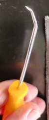
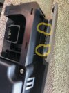
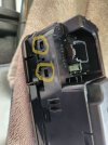
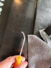
The trailer controller is a pain to switch over. You need to GENTLY pry up the black tabs, 2 top, 2 bottom, and stick it into your new Aux panel you get. You could try pushing the tabs of the trailer controller down, but I didn't want to damage those vs a panel that was getting tossed in a box.

This cheapo pick from ol' Harbor Freight worked great to get in there:

20241219_152117 - Copy.jpg


There's two tabs on top hidden by the trim, see here:

20241219_151925_highlighted.jpg


The tabs on the bottom are easy to get to:

20241219_151918_highlighted.jpg
 

Attachments

  • 20241219_152117.jpg
    20241219_152117.jpg
    98.6 KB · Views: 2
Last edited:

Aux Switch Harness (making your own)​

===================================================================================

Summary of Parts/ Materials
*NOTE: Thanks to the continued use/ influence of old Diamler, it uses German style/brand TE Connectivity Branded pieces

Connector/ Plug/ Male : Is the OEM Harness Conector that plugs into Aux Panel, good if you break the OEM plug or making pigtail y-cable
- 1456989-3
Pin/ Terminal : For OEM Harness Plug that plugs into Aux Panel & for the 1456989-3 plug
- 1393365-2

Connector/ Plug/ Female : Is the type of plug ON the AUX panel, used if making a pigtail y-cable
- 6-1419167-1
Pin/ Terminal : For use in connector 6-1419167-1, used if making a pigtail y-cable
- 1438299-4


There's two basic ways I would suggest to do this:​

===================================================================================
1. Add pins to OEM plug
- Easiest method, just add pins to the OEM harness connector that plugs into the Aux panel, a bit cleaner.

2. Make a pigtail y-cable
- More difficult and requires more parts, but also easily removable if desired.

*NOTE: No more than 18ga wire! You are not running real power through here, just activating a relay via ground, suggest 20 or 22ga (higher the number, smaller the wire)


Materials Needed for direct into existing OEM plug version (NOT making a pig-tail y-cable):​

===================================================================================

1. Wire, 20ga, 6 conductor
- You can go MAX 18ga, but it's just a ground relay activator, you're not running the aux device accessory power through them.
- Get it as a bundle and make you life easier, something link this:
- I got a bundle of 22ga wire, and while it will work, I think it's just too thin and not high temp for in the engine bay, so go 20ga to max 18ga, but get high temp silicone sheathing
-- I'm trying these ones in 20ga, will just need to use automotive fabric tape and bundle them from here: https://www.amazon.com/DONOKY-Gauge-Silicone-Wire-Spools/dp/B0BWGZ9LXT
-- 18ga version w/ 25ft should be enough here: https://www.amazon.com/BNTECHGO-Silicone-Flexible-Stranded-Tinned/dp/B09X466WH5

2. Connector Pins
- TE Connectivity 1393365-2
-- Buy extra, you need 6, get a 10 or 20 pack
-- via Mouser https://www.mouser.com/ProductDetail/TE-Connectivity/1393365-2?qs=CTuLUzlVTuEtINdpPCPYXw==
-- via Digikey https://www.digikey.com/en/products/detail/te-connectivity-amp-connectors/1393365-2/2300989

3. Connector - Male - Spare OEM Connector that plugs into aux panel
- TE Connectivity 1456989-3
-- Buy a spare or two!
-- Just in case you have some blanked or mess it up
- via Mouser https://www.mouser.com/ProductDetail/TE-Connectivity/1456989-3?qs=JgOBn5pVFopc4V%2BCpl9Rng==
- via Digikey https://www.digikey.com/en/products/detail/te-connectivity-amp-connectors/1456989-3/5437181

Looks like:
=====oem cable======[OEM PLUG][AUX Panel]


Additional Materials if making as a pigtail y-cable​

===================================================================================
- Make sure you have (20) 1393365-2 from above
- Make sure you have (3) 1456989-3 from above

4. Connector - Female
- TE Connectivity 6-1419167-1
-- Connector/ Plug/ Female : Is the type of plug ON the AUX panel, used if making a pigtail y-cable
-- Get 2 in case you mess one up
- via Mouser https://www.mouser.com/ProductDetail/TE-Connectivity/6-1419167-1?qs=%2BQd/V%2BJdpmfervpJ4EXzIA==
- via DigiKey (not avail)

5. Connector Pins
- TE Connectivity 1438299-4
-- Pin/ Terminal : For use in connector 6-1419167-1, used if making a pigtail y-cable
-- Get a full 16 or 20 pack
- via Mouser (100pk is min) https://www.mouser.com/ProductDetail/TE-Connectivity-AMP/1438299-4-Cut-Strip?qs=j%2B1pi9TdxUaA2JronglQGw==
- via Digikey https://www.digikey.com/en/products...4/2301037?s=N4IgTCBcDaIIwBYDMAOMBOdBaBIC6AvkA


Looks like:
=====oem cable======[OEM PLUG][NEW FEMALE PLUG]======pigtail=======[NEW MALE OEM STYLE PLUG][AUX Panel]


Process for using the existing OEM connector​

===================================================================================

1. Prep a length of wire​

Give yourself 6-10ft of bundle wire to run from the panel to the relay box under the hood (you'll feed this through the firewall eventually).
** Have an idea of where you will place your relay box where these will connect into. If you install it at the front of the engine bay, you might need a bit more length to get it to reach. **

2. Determine color/ aux port wire combination​

Decide what colors will go to which aux button
Example with the standard color bundle, I set it as:
Aux 1 - Green
Aux 2 - Orange
Aux 3 - White
Aux 4 - Black
Aux 5 - Red
Aux 6 - Yellow

3. Install connector terminators to your cable​

Open one end of the cable and start putting on your terminators.
Bonus: Check each connector to the other end of the cable for continuity. Use that trusty volt meter to check resistance or if your meter has it, just set it to make a sound for continuity, beep and it's good.

4. Prep combining your new aux lead wires and the OEM wires and connector​

Slide a piece of shrink wrap around your OEM cable and new cable and terminations (fold the OEM one over length wise to get it to fit), or skip and use a small zip tie later.

5. Install the terminated ends into the connector​

Check your OEM cable orientation.
Check it again.
Check it ONE MORE TIME and start inserting your pins into the CORRECT AUX PIN LOCATIONS one at a time.
VALIDATE each pin as you insert and location with the image of the plug.
Check, check, and check again.

6. Run your new cable to the firewall location​

Dress in your cable to the firewall location you will push it through.
Make sure not to interfere with moving HVAC parts, damage other cables.
Use small zip ties to secure it in place/ out of the way.

7. Run it through the firewall​

Push it through the firewall into the engine bay.
- Can use the location used where the power running board wires are pushed through.
- Try to leave a drip loop if possible.
- If you never ran cables through the firewall before, def look up videos. A snake or metal coat hanger and electrical tape are your friends here, as can be some cable glide like Ideal Clear Guide so it slides through and dries later, better than using grease or silicone grease.
Bonus: Use some black silicone caulk around the area (clean it up first) where you pushed it through.

Here's a snap from the powered running board install page:
firewall-wire-routing.JPG

8. Route to your Relay Box location​

Determine wire routing to your Relay box and secure with zip ties.

9. Prep cable, add your relay box terminators, and install to the correct location for of each Aux wire lead to each switch relay in the box.​

Get your PDU/Relay Box ready and terminate these wires there to each pin 85 location of each Aux relay (covered more in depth below)
Your Relay box placement under the hood will determine how much lead wire you need. Did you make it long enough?


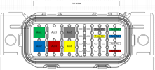
Here are some handy images for reference:
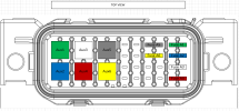
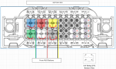
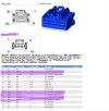
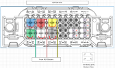
This first one is CRITICAL for ID'ing the pins and the orientation:
7688557F-4A07-4F74-9C86-DA076C3D5798.jpeg

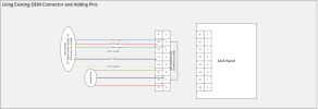
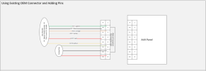
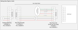
Made a quick ref diagram for using the exiting connector:
truck_wiring_AUX-PINOUT-CABLE_r1.PNG

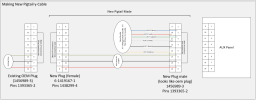
Made another quick ref diagram for adding a pig-tail Y-adapter:
truck_wiring_AUX-PINOUT-CABLE-PIGTAIL_r1.PNG

If you need a higher res image, I saved it to a PDF, I can send it, just DM me.
 
Last edited:

Power Distribution and Relay box if making your own​

===================================================================================

Option to consider:
Do you want to run a single wire power line connector for your aux accessories or do you want to run two wire with power and ground?
How "clean" is the chassis ground on the 1500's?
How sensitive is the system chassis ground to some junk LED/other cheapo accessories we may run that way?
If you don't care, a single wire power connector is all you need from the relay box (similar to the OEM upfitter setup).
If you do care, or want it easier to install accessories without worrying about chassis ground, then use a two-wire setup for the aux plug - one from the relay box for power, the other from a ground bus bar.

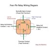
Remember, you are making a ground trigger relay where the connection of the ground circuit activates the relay and carries minimal current to activate the relay (thanks for the image TrueMods.com), explained with the relay image below:
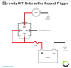
31e4a5382e0085dedb81cfee930a0123.png


Materials Needed for PDU and Relays​

===================================================================================

1. Relay Box w/fuses
There are several options here from buying a kit, using full size, using mini, building your own, etc.
Personal Opinion: Build your own mini fuse and mini relay box. There's some amazing options from Little Fuse or from GEP

1a. Buying a kit
- There's a decent amount of options here, True Mods is a popular one with the Jeep crew, also seals well:
-- https://www.truemods.com/epspwr0312-waterproof-relay-box-w-relays-fuses-accepspwr0313, max 30 Amps per relay, (theoretical max 180amps)
-- via Amazon Amazon.com,

1b. Build it yourself (mini-fuses and mini-relays)
- Really, the best way to go, you can customize it, make it bigger or smaller, etc.
- These both use Metri-Pack Series 280 FEMALE terminals in the box, with the related cable seals that crimp with the terminal based on wire size
- They even have lime green plugs for the unused spaces on the back of the box
- Make a diagram to save yourself time and heartache
- Planning is KEY!
-- GEP: PDM-R4A01 | GEP Power Products (48-position works if using SPST mini relays (only take 4 spots), where SPDT takes up 6 spots)
-- Little Fuse: PDM21001LXM (via Amazon.com)
- When building, make sure you also get the right amount of relays, fuses, 280 style female connectors, cable seals, and blank plugs.

- Make sure whatever you get, it is fused and don't forget to GET fuses and relays if they don't come with them.
- For the love, please use proper rated fuses for each aux item, the vendor of your accessory should tell you what that is
- CEAutoElectricSupply.com is an AWESOME resource, they even have a configurator for your box setup!
- Another good resource is https://www.customconnectorkits.com/


2. Power Distribution Bar/Unit (PDU)
- This helps get MAIN power from your battery to each of your relay fuses used to power the Aux connected accessories
-- Another popular option, Amazon.com
- ** You can skip a PDU if you'd like to run a power line to the box location in 4ga, and then solder and seal chaining each 16ga wire off as a pig tail to each fuse. It's less components but can be hard to seal the connections. Again, depends on what you plan to run off your aux panel. SOME boxes also come with a PDU integrated into it, so again it really depends on what you buy and what you want to do.


2a. (OPTIONAL) Ground Distribution Bar/Unit (GDU)
- Only if you are planning to run 2-wire for the Aux plugs under the hood to connect to your accessories to include BOTH power and ground
-- Can use same as the power one - True mods Amazon.com
-- or this 4-Inch 6-Way Ground Power Distribution Block - Black
-- or this Amazon.com
-- or this https://www.amazon.com/Distribution-Terminal-Battery-Negative-Insulated/dp/B087QVY4FY/


3. Power Wire - Main - from battery to power distribution bar, 4ga
- Depending on where you put it will vary your length needed.
-- Get at LEAST 10ft of 4ga
--- This is an option if you just want it all and dont need to worry about finding other crap: Amazon.com (Wire, tools, crimps, fuse block etc)
--- Amazon.com (Wire, tools, crimps, even a fuse block etc)
--- Amazon.com (Just wire)
--- Amazon.com (Both black and red)


3a. (OPTIONAL) Ground Wire - Main - from battery to a GDU, 4ga
- Only if you plan to run 2-connector aux connections under the hood and want both power and ground to each one
- Suggest a package with the power wire above, it'll be cheaper and easier


4. Fuse/breaker - Power Wire - Main - Inline from battery to PDU
- You should fuse this main battery connector from the battery to the PDU like you were setting up an audio system
- Protects the truck and relay system.
-- Find one encapsulated to protect both it from the elements and from accidental touching of you/ grounds
-- If MAX of potential capacity of 6 fused aux connections x 30amp = 180amp. I would not push that much power through this personally, like 100-150 amp fuse
- Breaker Style in 150 (these tend to fail in heat environments under the hood)
-- https://www.amazon.com/Nilight-Resettable-Overload-Protection-Amplifier/dp/B0CFY6J6DW
- Fuse Style, Type ANL
-- https://www.amazon.com/Skar-Audio-Gauge-line-Holder/dp/B0BW4TLBST/
-- Amazon.com
-- Amazon.com


5. 14ga Red Color Power Wire
- For wiring in the PDU to the Fuse, Fuse to Relay, Relay to Aux Connector
- A quality tinned copper marine stable power wire is ideal, as it'll stand up to corrosion more
-- Options with both red and black if you also do a dual plug with ground for the under hood aux connects
-- https://www.amazon.com/OPLIAT-Wire【Red-40ft】High-Silicone-Degree/dp/B09XB256SN
-- https://www.amazon.com/Wire-30FT-Oxygen-Free-Electrical-Automotive-Lighting/dp/B0D1K6QLV5


6. (OPTIONAL) 14ga Black Color Ground Wire
- For wiring in the GDU to the Aux Connector
- Same as above, if doing this, buy a combo to save money


7. AUX Output Connectors
- I prefer Delphi style connectors to DT or DTP style connectors
- Of those, prefer the Delphi Metri-Pack style connectors, they seem to seal better and if you get a quality one, the clips don't break as much.
-- **You can probably build a whole parts kit of everything you want from CustomConnectorKits.com and add what you need and not these pre-done kits from Amazon sellers.
--- For example, you can built a 8-plug kit (you only need 6, 2 spares) with even the blank plugs for the adapters and a tool for $55 shipped:
--- 1734804759126.png
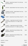
-- Single Wire Metri-Pack Waterproof connectors
--- via Amazon https://www.amazon.com/Metri-Pack-Waterproof-Connector-Terminals-12-20awg/dp/B0D5CL9VHH/
-- Double Wire Metri-Pack Waterproof connectors
--- via Amazon https://www.amazon.com/3-Pack-Metri-Pack-Waterproof-Connector-Terminals/dp/B0CDVFG3GQ/
--- these ones are for higher gauge in a 5-pack, may work - may not, but here's a link anyway https://www.amazon.com/Metri-Pack-Waterproof-Connector-Terminals-12-10awg/dp/B0D2CZWHXM
-- Double Wire Alternatives to Metri-Pack
--- via Amazon https://www.amazon.com/MUYI-Waterproof-Electrical-Connector-Terminals/dp/B01FP1HXHQ (unk amp rating)
--- via Amazoo https://www.amazon.com/Twippo-Connectors-Waterproof-Automotive-Electrical/dp/B0BFZZHGXJ/ (20a rating)
--- via Amazon https://www.amazon.com/Waterproof-Automotive-Electrical-Connectors-Connector/dp/B0BMXFBZ6R (9.5a rating)
-- You can also cheat and if not using ground wires for each connector, can just get a 6-wire plug as a kit here:
--- https://www.customconnectorkits.com/collections/mp280-connectors/products/12059573

8. (OPTIONAL) Make blank plugs for unused Aux connectors
-- Which ever version you use, you should make custom plugs for the Aux pigtails not it use in the engine bay to keep them clean.
-- For example, these MIGHT work as custom caps (just silicone in the wire ends before installing) for the 2-wire https://www.amazon.com/12015792-Complete-Connector-Replacement-Weather/dp/B088KDVG32, but unsure.
-- Worse case, buy extra packs of your connectors, or if using the 2-wire female plug off the Aux Relay Box, you can likely get these: https://www.mouser.com/ProductDetail/Aptiv-formerly-Delphi/12052643?qs=xyz6lfZ1ktJwBsyeXuJjCQ==


Process​

===================================================================================

CRITICAL: Do NOT have battery power connected to any of these wires while working on your wiring.
CRITICAL: You should also remove the Positive Battery terminal while working on this.


Before staring anything, having an idea of where to have this laid out is important, as it will help you guesstimate on wire lengths, positions, and so forth. Do you want the fuse box up in the front by the other fuse box? Do you want it back where the OEM Upfitter places it on the drivers side close to the firewall? You location preference matters, as it directly impacts your wire layout and lengths. Example image below of spots you can put it.

ram-1500-enginebay.jpg


NOTE1: For your actual Aux power connector where you will plug your accessories into, I would suggest using the female plug for the vehicle side connection. This usually has the large opening and shroud around it. Many of these may have blank plugs available for them or make your own. This is also normal manner of a harness plug side to many vehicle harnesses.

NOTE2: Each step you make a termination or do something with a wire - TEST IT. Use your volt meter and check for continuity with a ohm test or continuity "beep"? Troubleshoot a few seconds now or troubleshoot for days later. With experience comes knowledge. :)

Bonus: You should solder/tin any crimped end you make (either before crimping, or do it once crimped, people have preferred methods).
Bonus: Add dialectic grease to plugs/terminals and then wipe excess, helps with corrosion.
Bonus: Add fabric electrical tape to wrap wires and then wire loom of your choice and use shrink tube and heat to hold the wire loom in place, don't melt it!


1. Have your Fuse, PDU, and GDU locations laid out​

- Can likely mount your fuse, GDU, and PDU to where you want them.
- You'll need access to the back of your Fuse/Relay box still for terminating, so don't mount it yet and helps if you are doing this on a bench.

2. Prepare your power line from the battery to the fuse.​

- Cut your 4ga red wire to the correct length
- Use the correct terminal and strip and crimp one end for battery connection (know the terminal you will be using on the battery!)
-- Did you forget the heat shrink?
- Slide one (or two if you forgot) pieces of heat shrink on
- Depending on the type of fuse block you got: either strip and crimp a connector on the other end -OR- if bare and no terminator, tin (solder) this end to help with getting a terminal screw to bite.
- If you ignored the safety piece and connected it to the battery to get proper length set and to ensure connection, NOW DISCONNECT IT.

3. Prepare your power line from the fuse to your PDU.​

- Same process as above: red 4ga, cut to length, crimp, tin, shrink tube, cable wrap, etc.
- You can dress in and connect these as well.
- You have it disconnected from the battery, right?

4. (OPTIONAL) Prepare your ground line from the battery to your GDU if using the 2-wire Aux accessory connector plugs​

- Same process as your power line, except use the black 4ga wire.

5. Prepare your power lines from the PDU to the Fuse Box​

NOTE: This can be done on a workbench to make this part easier since you haven't mounted the Fuse/Relay box yet.
- Cut (6) 14ga red wires with some extra slack for running between your PDU and the Fuse location for each AUX connection.
- Strip and crimp the fuse side, tin, heat shrink as appropriate for your fuse box.
- Bundle and dress in the cables together.
-- Bonus: Tape and heat shrink each cable as high as possible to the fuse crimp, and at some point, bundle them together with a piece of heat shrink tubing and the fabric tape.
-- Bonus: Add loom sleeve to help abrasion resistance to this bundle with the tape.
--- (I'm a cable nerd and like neat and dressed in cables, years of fixing audio installs, data networking, etc made me this way and I can't help it, haha!)

NOTE: these next steps can be done later once the rest of your Fuse/Relay box work is done if doing it on bench.
- Run this bundle to your PDU.
- Cut to proper length and add your PDU terminators and shrink tube to EACH wire/terminator.
-- Suggestion: Finish fabric taping the bundle to the proper location to NOT place too much strain on them once connected.
-- Suggestion: Trim any loom sleeve that's too long, add a shrink tube and heat/seal it.
-Bonus: Add labels to the PDU end of the wire so you know which Aux fuse it runs to!

6. Prepare your powered relay wires for Terminal 86​

Note: This is what needs power to activate the relay when you toggle the AUX ground wire
Note: Most people (as also noted in the diagrams) piggy-back this from the main power terminal 30 to this pin 86 on ground activated relays.
Note: It will be a short cable with one end terminated with the 86 relay terminal connector and crimped into the terminal in the next step for terminal 30, making a jumper.
Note: This reduces wiring complexity, extra wires used around the engine bay, and also cuts power to the relay completely if the fuse pops or you pull the fuse.
- Cut (6) red 22ga wire to about 6" in length to give yourself room to work, they'll only be 1-3" when done.
- Strip and crimp the terminal for the #86 relay to one end.
-- Highly suggest soldering these ends as well
-- Did you forget your heat shrink?
- Do not install this terminal in the relay block, you do that in the next step.

6. Prepare your Fuse connection to the Relay terminal 30​

Note: This is where having your Fuse/Relay box on a bench will save you.
Note: Make sure you note and match positions for Aux#, to relating fuse #, to relating relay position
Note: Start with the first fuse and start working your way down the row.
Note: This is also where you will jumper the terminal 86 lead into the terminal 30 crimp connector.
- Cut (6) red 14ga wires about 14"-16" in length.
- Strip and terminate each with the other side fuse holder terminator.

Next work each fuse/realy as a pair.
- Determine length from fuse to matching Terminal 30 on the relay terminal, keeping in mind adding the terminator and cut to length (you can have some slack here).
- Strip the wire and PREPARE to terminate with the relay 30 terminal.
- Determine the length needed for the pervious made 22ga terminal 86 wire lead to insert into block and add the other end to this 30 terminal
- Cut the terminal 86 lead to length, strip and ADD to the 14ga fuse wire in the 30 terminal connector.
- With both 14ga fuse wire and 22ga terminal 86 wire in the new terminal 30, crimp it.
- Did you meter test it?
- Double check relay terminal position and insert each terminal 30 and terminal 86 in the correct positions for the relay.
- Did you put them in the right spot?
- Did you meter check it again?

Finally double and tripple check your work:
- Fuse position matches relay position.
- Relay connector position matches proper relay connector location.
- You meter checked them right?

7. Prepare your Aux power wire for Terminal 87​

Note: Length here will vary depending on where you want your Aux Accessory plug to be.
If your relay box is back by the firewall, and so are your connectors, your leads here will be short. If it's up by the front, these will need to be long if you run your Aux connector back to the firewall, ans so forth.
- Determine length of 14ga red aux power wire you will need to go from your relay box terminal 87 to your Aux power connector and cut to length.
- Strip and crimp your terminal 87 wires.
- Bundle, tape, wrap, etc as appropriate.
- Did you meter test it?
- Now strip and crimp the Aux plug terminal end you are using to the other side of each.
- Insert terminator into the connector.
- (Optional) if using 2-wire connectors, double check Aux connector location for which side should be power, and insert it into the correct connector spot.
- Bonus: Label each to know which one will go where, so you don't need to continuity test each later to find each one, add a perm label to always know and help yourself and others later!

8. (OPTIONAL) Prepare your ground lines from the GDU to your Aux connector location​

Just as with step before, you need to determine the length of these but now from your GDU to the Aux connector if you are using the two-wire version of both power and ground.
- Determine length of 14ga aux black wire to go from the GDU to the AuX connector location.
- Strip and terminate one end of each with the GDU terminal connectors
- Did you forget the heat shrink?
- Strip and terminate the other end with the Aux connect plug terminal you will use.
- Bundle, tape, cable loom, etc all these new wires together and run them to the Aux connector location
- Double check Aux connector location for which side should be ground, and insert it into the connector.
- Bonus: Label each to know which one will go where, so you don't need to continuity test each later, add a perm label to always know and help yourself and others later!

9. Make sure all your newly made connections are installed, cables dressed in, circuits tested (no battery yet!).​

- Double and triple check continuity for all complete circuits (both power and ground).
- Check continuity from PDU main lug to fuse power side.
- Insert a temporary 5amp fuse and test from the PDU to the Aux connector power for each circuit.
- (Optional) If using 2-wire, check continuity from the battery ground terminal to your ground of the Aux connector.

10. Connect battery and volt test each circuit.​

- Using that same 5amp temp fuse, test the voltage for each circuit at the aux connector (positive lead on Aux power connector, ground lead to a ground or battery terminal).


11. (Optional) Make your Aux connector plugs​

Not required, but highly suggest you make plugs to keep your Aux connectors clean and corrosion free. You may be able to locate a specific plug for your connector type, or just buy extra connectors, fill in each wire side with some high temp silicone (and let dry), then use them as a plug.


Here are some basic diagrams for both 1-wire and 2-wire Aux connector installs (again, have a higher res PDF if you want it):
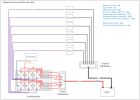
fuse-relay-pdu-double-wire.PNG

fuse-relay-pdu-single-wire.PNG
 
Last edited:

How to program the new Aux Switches to work​

====================================================================================
Once the buttons are set correctly, thy will function immediately and likely not show immediately under the settings on uConnect/screen.


If using JScan (in progress, still troubleshooting, it's missing an option for all 6 switches)​

Adaptation = Axuiliary Switches - settings
  • Auxiliary Switch Bank Module (ASBM) Present - On/Off : Active
  • Auxiliary Switch Bank Module (ASBMM) Present - On/Off : Active (may not need this one)
  • Auxiliary Switches in CSM On/Off
    • This is the option it has missing, "Switch option 3-6 buttons"
    • "Switch option 2-5 buttons" will not get you anything on the screen.
    • "Switch option 1-4 buttons" WILL get you 1-4 in the settings screen.
  • Auxiliary Switches Settings : Switch 6 option
Modules = Body Controller
Search for "aux" (These should already be set now, but validate)
  • Auxiliary switches customer settings menu : Switch 1-4 option / SWITCH_1_4 (This should be Switch 3-6 option/ SWITCH_3_6 once they update the app)
  • Aux Switch Configuration : Six Switches


If using AlphaOBD​

The following options need to be set:
  • CBC Features: Configuration Aux Switches PTO-SIX SWITCHES
  • LIN & Misc: ASBM Present - YES
  • CustSetMenu 1: Auxiliary Switches CSM Present - Switch 3-6 Option


Note1: Using either, you should do a BCM and Radio RESTART once or twice as well.

Note2: As with all things BCM and uConnection screen related, it could take up to 24 hrs to show for config options on screen.
 
Last edited:

Additional Links and other General Notes:​

===================================================================================

Build Code:​

  • The Build Code from MOPAR for the upfitter swicthes is the sales code of LHL.

Notes - Misc:​

  • Most items I used to build were built to max state/worst case.
  • I tried to keep all 6 Aux connection chains setup for a max of 30 amps. No way I'll run them all at 30amp, but gives me flexibility.
  • I would not run more than 100-150 amp range MAX through this.
  • 14ga wire will carry 32amps in chassis wiring, so max 30amp per relay/ max 30amp fuse

Additional Schematics:​


Videos:​

HotDamnRacing Youtube Videos, 3-part series of AUX switch install
1 -
2 -
3 -
 
Last edited:
Reserved
 
Last edited:
Correct Body Control Module and have it programed by your dealer (for 19-20)
Another option for 2019-2020 owners is I can flash their existing BCM into a 2022 BCM (if they can go with not driving their truck for a few days). It’ll save on the cost of a new BCM and dealer visit.
 
Awesome, adding it to the above as an option.
 
Awesome, adding it to the above as an option.

Great job and thanks Suli!!!!
Thanks Jimmy, as always you are the go to on these things!!!


Sent from my iPhone using Tapatalk
 
This is great, but you should have posted it in the modification section with the other how-tos. That way they'd all be in one location and then you could have the admins pin it. Maybe one of the admins can move it to the appropriate section.
 
This is great, but you should have posted it in the modification section with the other how-tos. That way they'd all be in one location and then you could have the admins pin it. Maybe one of the admins can move it to the appropriate section.
Yes! maybe a mod can move it
 
This is great, but you should have posted it in the modification section with the other how-tos. That way they'd all be in one location and then you could have the admins pin it. Maybe one of the admins can move it to the appropriate section.
Crap, I messed up, I can always just re-create it there if need be if the mods can't move it.
 
Here is my implementation of all DIY setup.
Get more than the required amount as it is easy to mess up
I use MOUSER and Amazon for all my parts mentioned

Pins:
1393366-1 Get 10 or more
1438299-4 Get 5 or more

Connectors (You need one of each since I did a Y cable):
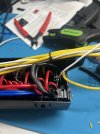
6-1419167-1
146989-3

If you are NOT used to doing this I would recommend getting spares just in case.

Crimping Tools:
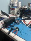
Haisstronica Crimping Tool for Non-Insulated Open Barrel Terminals Receptacles,AWG 20-10 Ratchet Wire Crimper Tool,Wire Terminal Crimper HS-5327 https://a.co/d/01p9dYo
Wire
DEKIEVALE 18 Gauge 6 Conductor Electrical Wire, 10FT 18AWG Black PVC Stranded Tinned Copper 6 Wire Cable, 18/6 Cord Extension Cable https://a.co/d/exoi7av
Relay box:
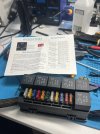
RVBOATPAT 12V Fuse Relay Box with 6 Relays and 11 Way ATC/ATO Blade Fuses, Pre-Wired Fuse and Relay Box 12 Vlot Relay Fuse Box Block for Automotive Marine Boat https://a.co/d/1zbHaJA
Connectors:
Twippo 800Pcs 50 Sets Waterproof Automotive Electrical Connectors Automotive Electrical Wire Connectors Plug Kit 1/2/3/4/5/6 Pin Waterproof Connectors https://a.co/d/d7R8Hon

Steps:
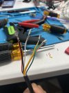
1. Start by adding pins to all the wires. I used 6" of wires.
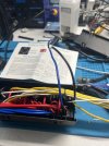
1734372579377.jpeg

2. Insert the wires into pins based on the diagram provided in post #4.

1734372740735.jpeg


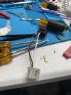
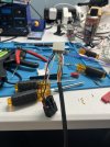
3. Add the aux Relay wires to the connector and take note of what color wire is being used for which switch.

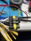
1734372837522.jpeg
The gray connector plugs into your switch panel and the black connector goes to factory connector that originally plugged into switch panel. We are just adding this in between the factory harness and switch panel.

You have successfully completed the harness for truck interior. The black wire with the 6 aux switches wires is 86" long. Do NOT add any connectors to the end of it yet. Doing so will cause you routing issues.

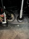
4. Run the black cable with the 6 wires through this grommet. It already has the transmission neutral cable running through it in center. Its to the left of steering shaft.
1734373377069.jpeg
NOTE: Make sure the cable isn't touching the steering shaft as it will wear the the wire out over time and cause a short. I sealed everything up around the grommet and wire using silicone to keep water out.

5. Under the hood, the grommet should be in the brake booster area and you can fish the wire out from there to the left front headlight area and secure it with zip ties along the way.

1734373932612.png


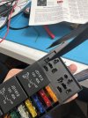
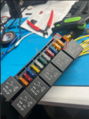
6.This is the relay setup I went with. Its 6 fused relays plus 5 additional always on fuses. You don't have to go this route but I just wanted to be able to expand my setup in future for other things.
1734374136215.jpeg

This is how a relay setup should be based on the pins:
1734374280985.jpeg

Pins 85 and 86 don't have a polarity but my OCD got to me and I decided to modify the relay box to make it like the picture lol. It will still work as is without this change.

7. OPTIONAL: Swap out pins 85 and 86 terminals in relay box.
Since most relay setups are +ve switched and our system is -ve switched.

Before swap:
1734375247243.jpeg

All we need to do is swap the black and white wire on each relay.
We can remove the relay and using a pick we can get the terminals out to do the swap.
There is a tiny cutout on every pin we just need to stick the pick in there and push towards the pin to release them.
Gently keep wiggling the wire and don't pull wire too hard.
I'm using a tweezer here in picture but a pick would be the ideal tool

1734374927991.jpeg

The black wire is daisy chained so you can remove it all and and then just swap its position with the white wire
1734375082676.jpeg
 
Last edited:
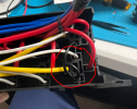
After Swap you should end up with something like this:
1734375565960.png

Note the difference between the left relay and the one circled.

8. Now that we have relay setup I recommend adding a fuse to this setup since by default all the relay coils are directly connected to battery. Just in case something was to happen with relay coils due to water or overload or whatever. In this setup we do have 5 additional fuses, so I decided to use one. I take one of the blue wires(preferably fuse one just because its easy to remember lol)

1734375933032.jpeg

Connect the black and blue wire and heat shrink/tape it.
1734376042894.jpeg

Now coming to the fuse. I did a test on relay to see the coil power draw and typically its between 0.15-0.20A.
1734376149858.jpeg
We have 6 relays a and lets say we have them all ON so the power draw will be 6*0.20 = 1.2A
1734376268278.png
I used a 5A fuse that was already in the box and swapped it out. We could have gone with a 2A fuse but I didn't have that and the 5A is just as sensitive and the wires are thick enough so if something were to happen the 5A fuse will blow before anything else.

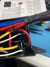
9. Now its time to clean things up and move all the output and input wires to one side. the relay box does come with the wires labelled for relays. We can start adding the connectors from Amazon I have mentioned.
1734376748875.jpeg

The connectors have numbers on them too so i matched those up to relay numbers.
1734378084339.png
I used 6 pin male, 6 pin female, and 4 pin female connector. I used a 6 pin male and female instead of using same of the two to make it fool proof lol just in case someone else can't plug things wrong.

Once you button things up and clean up you are all set to go install it.

10. Under the hood we can add the 6 pin female connector to our black wire that is connected to our aux switches and match up the colors on black wire to the numbers on the connector with white wires.
1734377211700.jpeg

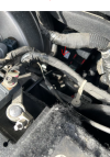
Lastly we just hook the red wires up to battery.

1734377664685.jpeg

As far as mounting goes, this box lines up with these ground post on one side and we can use some aluminum bar strips from hardware store to make some mount setup. Zip ties will do just fine as well. If messing with the ground posts be careful as these need to be connected back properly and a bad connection will cause electrical gremlins.

1734377604908.png

There you have it 6 fuse and switched relay setup with 4 always on outputs.
 
I like that you placed it up front with the other fuse box to make it easier to get to.
 

Users who are viewing this thread

Members online

Back
Top