5thGenRams Forums

Register a free account today to become a member! Once signed in, you'll be able to participate on this site by adding your own topics and posts, as well as connect with other members through your own private inbox!

How To: Adding OEM Upfitter Aux Switches on 2019+ Ram 1500 (DT)

Added more details if you want to build your Fuse/Relay box with mini-relays, and mini-fuses in Post #4 above. There's some really great units you can build and customize to just how you want it, even larger (or smaller) if you want. Little Fuse and GEP have some great products.
 
Made a table of contents to make first page navigation easier.
 
Added screen/radio pics and details for the radio version also having bearing on if you can see 4 or 6 switching in the settings menu on the radio.
 
Here's some good images of my pigtail building

Made my new wire harness from individual high-temp silicone 20ga wire, wrapped with Tesa tape (fabric electrical tape):
1735751480353.jpeg

Marked the cables of where to cut/ strip/ crimp:
1735751555524.jpeg

If your crimper bends these slightly like you see here, just a needle nose to straighten them out, or they wont fit the connector:

1735751689065.jpeg

Once done, use some heat shrink on the end to bundle them up (do NOT go any shorter then this or you wont be able to have enough movement to get them into the connector on the OEM harness. I also made a label here and used clear heat shrink tube on it to seal it on:
1735751801891.jpeg

My trusty Fluke 77 and my Brady cable labeler. Make sure you continuity test each lead once crimped.
1735751862200.jpeg
 

Attachments

  • 1735751630567.jpeg
    1735751630567.jpeg
    107.8 KB · Views: 4
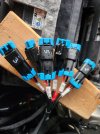
If you are not making a pigtail and inserting into each plug, don't push them all in yet, just place them in and double check your pin locations (they are keyed to go in a certain direction:
1735752162488.jpeg

Next, use a small needed nose and push them in one by one fully by row. They will fully seat, and check the connector face as you can visually see when they have set all the way, secure it with zip ties to the OEM plug.
1735752334817.jpeg

Run it from the back of the radio through the drivers side of the cab, watch for sharp edges and use other harnesses to secure it along the way, staying clear of accelerator pedal, steering column, etc. I ran it behind the fuse block under the steering wheel and secured it to make sure it's out of the way (driver seat is towards the top of photo):
1735752523844.jpeg

This is where you can run it through the firewall. This is where the OEM Power Sidesteps also have you feed through the firewall (not the hood release cable spot, you can see that in the bottom right of the picture. That box is actually the power side steps controller.
1735752690012.jpeg

Another picture, it's more of a rectangle rubber plug with a round on the top, a lot of cab wires run through here
1735752810562.jpeg


Here is where you'll come into the engine bay. If wiring it all in now, leave a short drip loop (section of cable that hangs down below the exit here).
1735752956399.jpeg


I left mine bundled here for now while I make my fuse/relay box. If you are running it, pull the front driver plastic fender well and run the cables there behind the battery box if you are running it to the front of the engine bay. Look at the OEM powered side step instructions on this, they describe it well how to do this.
1735753101765.jpeg
 

Users who are viewing this thread

Back
Top