HAL9001
Well-Known Member
- Joined
- Nov 10, 2020
- Messages
- 336
- Reaction score
- 627
Edit: I've updated all the information here to a much more comprehensive thread covering both the internal and external fuse panels. Please see this thread for the update and a lot more information.
I was installing a Dash Cam and a Radar Detector in my new 1500 and I needed to find a fuse with constant power and one with power only when the engine was running to tap into. It's ridiculously difficult to locate specific fuses on the internal fuse box because they're labeled so poorly in tiny black-on-black characters and hardly any are labeled.
So, I decided to take the time to label each fuse location for future reference. It's very useful so I'm posting it here if anyone else can use it. It's always good to know where each fuse is and what it does especially if one blows while you're on the road RVing or on vacation.
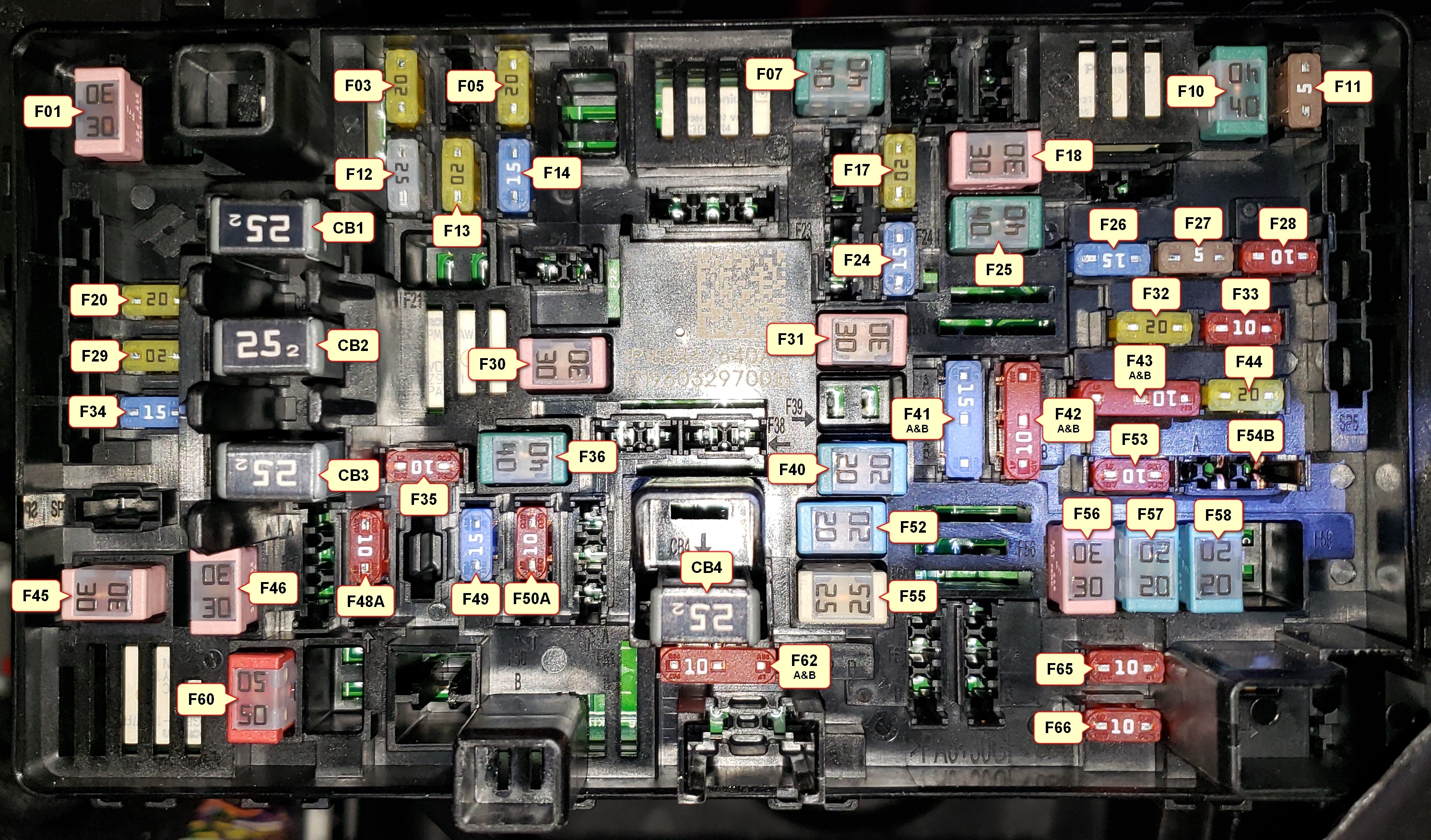
This is from a 2021 1500 Limited but it should be close to other 2019-2021 1500's as well with some fuses added or missing depending upon what options you have.
You can find a description for each fuse starting on page 460 of the owner's manual. I've also included this info as an attachment below. If you store this on your smartphone or print it out and keep a copy in the truck, you'll have a much better reference for the fuses if you ever have any problems.
It's also interesting and important to note that RAM used three different types of fuses in the Internal Fuse Box.
They use Micro2 Fuses, Micro3 Fuses, and MCASE Fuses. So, if you want to stock some spares, you'll need all three types.

There are also four 25 Amp Circuit Breakers, CB1 - CB4, labeled from top to bottom.
I was installing a Dash Cam and a Radar Detector in my new 1500 and I needed to find a fuse with constant power and one with power only when the engine was running to tap into. It's ridiculously difficult to locate specific fuses on the internal fuse box because they're labeled so poorly in tiny black-on-black characters and hardly any are labeled.
So, I decided to take the time to label each fuse location for future reference. It's very useful so I'm posting it here if anyone else can use it. It's always good to know where each fuse is and what it does especially if one blows while you're on the road RVing or on vacation.
This is from a 2021 1500 Limited but it should be close to other 2019-2021 1500's as well with some fuses added or missing depending upon what options you have.
You can find a description for each fuse starting on page 460 of the owner's manual. I've also included this info as an attachment below. If you store this on your smartphone or print it out and keep a copy in the truck, you'll have a much better reference for the fuses if you ever have any problems.
It's also interesting and important to note that RAM used three different types of fuses in the Internal Fuse Box.
They use Micro2 Fuses, Micro3 Fuses, and MCASE Fuses. So, if you want to stock some spares, you'll need all three types.
There are also four 25 Amp Circuit Breakers, CB1 - CB4, labeled from top to bottom.
Last edited:
![[IMG]](/community/proxy.php?image=https%3A%2F%2Fi.imgur.com%2FyFjLP9M.jpg&hash=3d7ac20c3ef6a69c7797590d7800b1b1 "[IMG]")