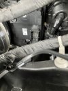
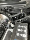
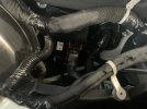
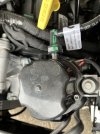
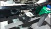
FROM THE 2019 DT SERVICE MANUAL:
08 - Electrical / 8E - Electronic Control Modules / MODULE, Active Vibration Cancellation (AVCM) / Description
DESCRIPTION AND OPERATION
DESCRIPTION
The Active Vibration Cancelation (AVC) system consists of the following components:
Component Index
OPERATION
The AVC system consists of two electronic actuators, two electronic sensors and the AVC controller.
The AVC actuators produce anti-vibrations to reduce Multi-Displacement System (MDS) vibrations above 1,300 Revolutions Per Minute (RPM). MDS is the “4 cylinder mode” for the 5.7L V8 engine. The AVC system is a key enabler for expanding the MDS operating range to improve vehicle performance and fuel economy. The AVC actuators function to
minimize vibrations on the vehicle’s frame at the frequency the engine is operating/running. The system works similar to Active Noise Cancelation (ANC). ANC operates on audible noise.
AVC operates on vehicle frame vibrations.
The AVC system is designed to improve the Noise Vibration Harshness (NVH) performance of the vehicle by reducing the vibrations received from the f
rame. The AVC actuator generates an equal signal in the opposite direction from the input vibrations received from the left and right correction sensors. This generated signal is sent to the left and right actuators mounted on the frame that reduce the vibrations in the frame.
AVC Module
The AVC module is mounted under the hood to the bulkhead on the driver side near the brake booster away from heat sources. The AVC module will operate the AVC actuators when the engine is in MDS operation mode as triggered by Controller Area Network - Chassis (CAN-C) message. The AVC module receives engine RPM as an input from CAN-C and a dedicated hard wired crank signal. The AVC module will adjust its output (frequency, phase, and amplitude) based upon the inputs. A software algorithm uses engine characteristics and vibration sensed by accelerometer to generate an output for actuators to produce the anti-vibrations.
CAN-C Inputs
- Commanded ignition switch status
- Engine RPM
- Vehicle Speed
- Odometer
- MDS active signal
- Vehicle configuration data for wheelbase length
- Vehicle drive configuration
CAN-C Outputs
- AVC failure display request to the Instrument Panel Cluster (IPC)
Hardwire Inputs
- Crank pulse signal
- Left AVC sensor signal
- Right AVC sensor signal
Hardwire Outputs
- Left AVC actuator operation
- Right AVC actuator operation
- Crank pulse signal to the ANC system
AVC Sensor/Actuator Assembly
The AVC sensor is attached to the AVC actuator mounting bracket and is not service separately from the actuator. The AVC actuator assemblies are mounted to the left and right sides of the vehicle frame behind the A-Pillars, under the driver and passenger door. The actuators produce anti-vibrations to reduce MDS vibrations between 1300 – 2300 RPM and are capable of an output of 90 N (20 Lbf) of force.
Hardwire Inputs
- Left AVC actuator operation request
- Right AVC actuator operation request
Regards,
Dusty
2019 Ram DT 1500 Silver Billet Laramie, Quad Cab, 2WD, 5.7 Hemi, 8HP75, 3.21 axle, 33 gallon fuel tank, 18 inch wheels. Build date: 17 April 2018. Now at 022440 miles.