5thGenRams Forums

Register a free account today to become a member! Once signed in, you'll be able to participate on this site by adding your own topics and posts, as well as connect with other members through your own private inbox!

Rear Heated & Ventilated Seat Connectors

Wow. We just need to trace the wires from the rear seat to the nearest junction. Color by color. We may end up having to splice into existing wires.
My problem is that there are no existing wires in my truck for rear heat/vent. If the junkyard would have given me the front portion of the harnesses, with the connectors intact (that plug in around the IP) I would have known what to do. I called back and requested a quote for the front part of the harnesses. Was told the body had already sold!
 
You REALLY need to get a three day subscription to techauthority, and pull all of the wiring schematics and connector locations.
On another note, is there a reason you didn’t just remove your current body harness, and install the donor harness instead? That would have been much easier if you already had a fully loaded donor body harness.
I just tried to subscribe to rechauthority. Site is asking for a dealer code. Is there another way to get it? Thanks, Brent
 
I had the console apart yesterday so I compared all the connections on the console harness to what my Bighorn harness has pinned. I discovered at least two circuits that need to be pinned for the rear seat heated and vented seats. Circuit A207 is the Fused B+ for the switches in the center console. Circuit D403 is the LIN BUS CBC 3 connection used by the seat switches and the wireless charger. I plan to add the fused circuit from the 12-volt outlet on top of the radio bezel. The LIN BUS circuit is the same BCM connector C5/E pin 45 connection in the Mopar instructions for adding wireless charging. So this can also be connected fairly easily. The remaining and unknown connection is circuit M124. I believe this may be the backlighting circuit for the seat switches, but I have not found it in any connector as of yet. See attached
 

Attachments

  • IMG_2886.jpeg
    IMG_2886.jpeg
    110.9 KB · Views: 22
Update, I found circuit M124 in another connector, but I have no idea where or what this connector is for.
 

Attachments

  • M124 circuit.png
    M124 circuit.png
    74.4 KB · Views: 18
I had the console apart yesterday so I compared all the connections on the console harness to what my Bighorn harness has pinned. I discovered at least two circuits that need to be pinned for the rear seat heated and vented seats. Circuit A207 is the Fused B+ for the switches in the center console. Circuit D403 is the LIN BUS CBC 3 connection used by the seat switches and the wireless charger. I plan to add the fused circuit from the 12-volt outlet on top of the radio bezel. The LIN BUS circuit is the same BCM connector C5/E pin 45 connection in the Mopar instructions for adding wireless charging. So this can also be connected fairly easily. The remaining and unknown connection is circuit M124. I believe this may be the backlighting circuit for the seat switches, but I have not found it in any connector as of yet. See attached
My notes are confusing to me now, a year later; But:
Pin 1 is not shown on the list I printed. List starts with Pin 2. But, for some reason I decided I needed it. It's a RD/BL and I "spliced to PK/YL in truck" .Probably should have connected it to a Power Distribution Connector? It does not appear to be "Lamp Driver" as your list shows (seems it's Fused Ignition). And, now, I'm wondering what's the difference amoung Pin 1-Lamp Driver, Pin 6-Panel Lamps Driver, and Pin 7-Reading Lamps Driver.
Pin 5, OR/DB was in the donor harness. and I added it to my truck Note says ":Heat Seat Switches X 2. " I didn't document where it originates.
Pin 8 is not on the list I printed; and I have no wire in that pin now.
 
Last edited:
Pin 5 comes from the BCM connector C5/E pin 45. It’s the same bus connection used by the wireless charging pad.
 
Pin 5 comes from the BCM connector C5/E pin 45. It’s the same bus connection used by the wireless charging pad.
I'm building harnesses and I'm stuck on one wire, so far. It's Pin 6 on XY435 A (Passenger Side) F919 PK/BU. I know it ultimately goes to Assy Power Distribution Center-Interior Pin 22. I can't find an intermediate connector. The same wire/circuit is at Pin 10 XY430A (Drivers Side). Do you have information? Thanks, Brent
 
Last edited:
If it’s the same circuit you should be able to just tap into it at the nearest junction. I guess I need to get a harness out of a wrecked Ram now too. I don’t have the wiring and pins to make it all from scratch.


Sent from my iPhone using Tapatalk
 
If it’s the same circuit you should be able to just tap into it at the nearest junction. I guess I need to get a harness out of a wrecked Ram now too. I don’t have the wiring and pins to make it all from scratch.


Sent from my iPhone using Tapatalk
Writing this just to document my findings and maybe help my thinking.

I found PK/BG F919 at both the seat connectors; XY410A Pin 4, and XY420A Pin 23. It seems to have just one feed--at XY330A under the center console. I had to splice it to feed both the seat connectors, above, when I installe the Front Seats. I plan to spice it again to get to the rear seat connectors, XY430A and XY435A. I have discovered that it feeds all 8 Seat Vent Motors. All at Pin 1. My concern is that it's 0.75 wire all the way through the system. So, one 0.75 wire feeding 4 branches. I'm hoping it's just a signal. All 8 Vent Motors have 3 wires. This F919 0.75, a 0.75 Ground, and a unique 0.35 Vent Motor Control.

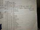
This is a fused switch ignition feed:

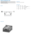
Pin Information​

CavCircuitGaugeColorFunction
1F9190.75PK/BGFUSED IGNITION SWITCH OUTPUT

XY430A also has additional power feeds:
1F9171.0PK/VTFUSED IGNITION
9F9181.0PK/BNFUSED IGNITION
 
This is a fused switch ignition feed:

Pin Information​

CavCircuitGaugeColorFunction
1F9190.75PK/BGFUSED IGNITION SWITCH OUTPUT

XY430A also has additional power feeds:
1F9171.0PK/VTFUSED IGNITION
9F9181.0PK/BNFUSED IGNITION
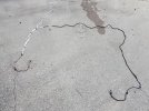
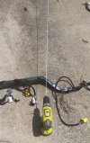
I got this far today. Used a drill to make the twisted pair for the CANBUS and it worked well!
 

Attachments

  • thumbnail (1).jpg
    thumbnail (1).jpg
    101 KB · Views: 28
  • thumbnail (2).jpg
    thumbnail (2).jpg
    234 KB · Views: 26
nice. I have used the drill trick on speaker wire
 
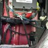
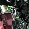
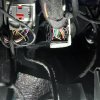
I finished and installed the harness I built. (This would have been so much easier to do the FRs and the RRs at the same time--but I don't think I knew RR heat/vent existed at that time)
1. PK/VT and PK/BN to XY331A. Surprised that F20 and F29 were present in the interior fuse box--for an option that's never going to be built.
2. WT/BU and WT to CAN IHS
3. PK/BU spliced at under center console. (Apparently the blower motors don't draw much current.) And 2nd Ground from XY430A.
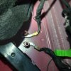
4. Grounds from XY 430A and XY 435A to ground lugs in rear floor of truck. Would have been much easier to just add ground screws; but I decided to do it the "right" way.

I thought the rears would be plug and play; just like the fronts were, but no such luck.
 

Attachments

  • Grounds in rear.jpg
    Grounds in rear.jpg
    150.6 KB · Views: 20
  • PK-BU spliced under center console.jpg
    PK-BU spliced under center console.jpg
    196 KB · Views: 21
  • CAN IHS.jpg
    CAN IHS.jpg
    167.5 KB · Views: 20
  • XY331A.jpg
    XY331A.jpg
    177 KB · Views: 20
Thanks for the follow-up. I need to either get the proper connectors or get a donor harness. It doesn't seem to complicated to me.
 
NEED HELP. 2022 BH. I completed harnesses to XY430A and XY435A and have make all the connections. I flashed ECUConfig 4-Heated Seats Present to YES. (this one is confusing; ECUConfig 3 is Front Heated Seats present; but 4 doesn't say Rear, just heated seats) . Also flashed Memory Rear Heated Seats Present and Memory Rear Vented seats Present both to Yes. Heat and Vent buttons in rear of console do nothing. Then I set Seats A-Rear Vented Seat Levels and Seats A-Rear Heated Seat Levels both to 3 Level (High-Med-Low-Off). Still switches do nothing. Then I set LIN and MISC--Left (and Right) Rear Climate Seat Switch Present to yes (I did this because the switches have a LIN BUS CBC 3 terminal. Still nothing. I would really appreciate any input on additional settings I need to make, or any incorrect settings I made. Thanks, Brent
 
I don’t have a harness, so not able to test. But I do see a setting called Seats A: Configuration Seat A. This setting is set to not programmed currently. Seats A seems to refer to the rear seats
 
I don’t have a harness, so not able to test. But I do see a setting called Seats A: Configuration Seat A. This setting is set to not programmed currently. Seats A seems to refer to the rear seats
Thanks. I just tried it. It was already set to 3 Level. Maybe when I set Seats A-Rear Vented (and Heated) Seat Levels both to 3 Level it also updated the Configuration setting?

I have verified 12V at each of the 3 Fused Ignitions on XY430A and the one on XY435; and that the 3 grounds are good.
Have not verified 12V at Fused B+ (RD/GN A207) at the switches. I'll check that tomorrow.
 
That setting should be programmed or not programmed. Mine is defaulted to not programmed


Sent from my iPhone using Tapatalk
 
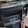
Operator error! There was no voltage on Pin 3 of XY360A. I traced it back. Last year, when I had run the A207 RD/GR to ASSEMBLY-POWER DISTRIBUTIONCENTER-INTERIOR C1, pinned it incorrectly. I didn't miss it by one pin--I was way off. I repinned it correctly to Pin 24 and voila had 12V at XY360A. Tried the switches and had half a eureka moment. The right side works; but nothing on the left. Strange.
 

Attachments

  • Heat!.jpg
    Heat!.jpg
    143.8 KB · Views: 13
  • Vent!.jpg
    Vent!.jpg
    108.3 KB · Views: 13
Well that is progress


Sent from my iPhone using Tapatalk
 

Users who are viewing this thread

Back
Top