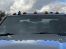
Do you know what circuit they tapped for power? Assuming they are on your running light circuit, but which wire and location did they tap?Laramie 1500 with lights that would normally go on a 2500 done by a dealer in MN View attachment 51528
Thanks
Do you know what circuit they tapped for power? Assuming they are on your running light circuit, but which wire and location did they tap?Laramie 1500 with lights that would normally go on a 2500 done by a dealer in MN View attachment 51528
Not quite sure, not sure if the “kit“ has a certain tie in spot or not. I’ll try find out.Do you know what circuit they tapped for power? Assuming they are on your running light circuit, but which wire and location did they tap?
Thanks


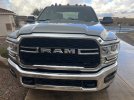
I wonder how those would look on my blacked out truck. I'm thinking maybe the smoked housings with amber lights wouldn't look too wonky. I wonder how long the batteries will last since the kits so expensive ($400)So I ended up going with the Cab Over America lights. I've never had a problem with charging and they hold a charge well and seem to last awhile. They only do On/Off. Work off the remote which is annoying but not a deal breaker... but if they had an upgrade to auto on and off with the truck I would do it in a heart beat. I had one stop working within a couple months and he messaged me back right away willing to warranty it but at the time it was a polar vortex in Wisconsin winter and I didn't want to go take it off in the cold and I just never got around to warranting it. Overall I love the look and they're functional. View attachment 171572
Sent from my SM-G986U using Tapatalk
I've owned them since Sept of 2020. In Oct 20 my one went bad (they offered to warranty for free but me being lazy kept forgetting to take it off and send it so I never warrantiesd it) but the other 4 are still working great.I wonder how those would look on my blacked out truck. I'm thinking maybe the smoked housings with amber lights wouldn't look too wonky. I wonder how long the batteries will last since the kits so expensive ($400)
Are they white or amber lights?I've owned them since Sept of 2020. In Oct 20 my one went bad (they offered to warranty for free but me being lazy kept forgetting to take it off and send it so I never warrantiesd it) but the other 4 are still working great.
Sent from my SM-G986U using Tapatalk
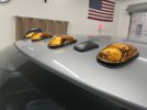
They're white with an Amber film and then the Amber cover. They're pretty darn close in color!Are they white or amber lights?
If they are amber do they match your blinker color?
Below is the actual set. From top to bottom:Are they white or amber lights?
If they are amber do they match your blinker color?


I’m interested in how you got power to F11. My ‘22 Big Horn didn’t come from the factory with a fuse in that location, and I don’t believe there is even bus bar (or whatever) connected to it underneath. But I could be wrong. If you found a way to make that happen, I would try the same thing. Thanks in adavance.I added them to my '21 Laramie EcoDiesel. I will do a HOW-TO thread shortly including pulling the Fuse box to wire them in to the Clearance light fuse (F11)
Malodave
View attachment 171836
The Circled fuse contact is the one that gets power with the Running lights.
View attachment 171837
I assume your set is a permanent, drilled in set? Threw me off, as there is no wiring required with the COA lights. Looks good!I added them to my '21 Laramie EcoDiesel. I will do a HOW-TO thread shortly including pulling the Fuse box to wire them in to the Clearance light fuse (F11)
Malodave
View attachment 171836
The Circled fuse contact is the one that gets power with the Running lights.
View attachment 171837

I’m interested in how you got power to F11. My ‘22 Big Horn didn’t come from the factory with a fuse in that location, and I don’t believe there is even bus bar (or whatever) connected to it underneath. But I could be wrong. If you found a way to make that happen, I would try the same thing. Thanks in adavance.
Thanks brother. I look forward to the write up!The Red Circle shows what side has power with the Running Lights. Pulling the fuse box is a strait forward and easy task.
Once I split the fuse box to get to the PCB, I drilled a hole in that circled location for the wire from an inline fuse holder.
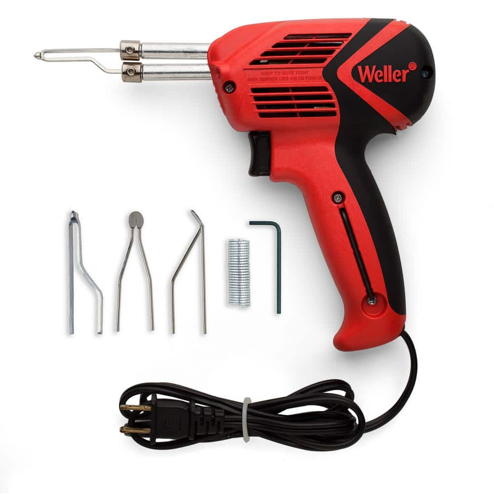
Pull the wire thru the hole and solder it to the PCB in that location. You will need a powerful Soldering iron as the hole
thru the PCB is not Thermally isolated. A 25 watt pencil soldering Iron will not cut it. I had a $600 Metcal iron and it
barely got enough heat to solder the wire. You would probably need a 100-250 watt soldering gun like your Grandfather used.
There are 3 grounding lugs right in that corner of the engine bay to use.
Something like this:
Weller 100-Watt/140-Watt Soldering Gun Kit 9400PKS - The Home Depot
Keep your work space neat and clean with the selection of this highly durable Weller large size Soldering Gun Kit.www.homedepot.com
Like I said, I will do a full HOW-TO thread to put in the Modification forum.
Malodave
I have included the Template I made with links to the Parts I used:
If you have a sunroof you will need to double check if it works for you.
You can get it printed at a Reprographics shop or some place
that prints blueprints. When I printed it it cost me about $10-12 for the two.