5thGenRams Forums

Register a free account today to become a member! Once signed in, you'll be able to participate on this site by adding your own topics and posts, as well as connect with other members through your own private inbox!

Adding Passive Entry: How-to

MayhemMOORE

Ram Guru
Joined
Apr 6, 2020
Messages
572
Reaction score
502
If you've seen the original thread on adding passive entry, HERE, you are likely well aware of the issues with getting it to work on the newer trucks that didn’t come with it from the factory. This thread will walk you through getting it to work on the 5th gen DT’s (and the HD trucks) just as it does in a factory-equipped truck, without requiring a visit to the dealer or the addition of the sales code to your VIN.

The success of this has been a collective effort with contributions from many individuals and they all deserve thanks since a lot of time and effort went in to laying the groundwork for this, both on the 4th gens and the new 5th gens, as well as helping test and troubleshoot to make sure all aspects of the system functioned correctly before pushing this out.

Standard disclaimer…If you are going to do this yourself, you are assuming all responsibility in the event something breaks or goes wrong. Also, any parts you add related to this are likely not going to be covered under warranty in the event there is a problem down the road. That being said, the whole process is fairly straightforward if you have basic mechanical abilities and a little patience for dealing with the door panels and wiring. Just be careful and take your time.

Clicking links below will take you directly to the specific posts indicated:

Post #1: Basic list of parts/tools required
Post #2: Door panel and handle removal
Post #3: Carrier plate removal
Post #4: Making the BCM changes in AlfaOBD
Post #5: 2019 & 2020 Rear Antenna
Post #6: 2021 Rear Antenna
Post #7: Part numbers for handles, caps, clips, terminals & connector housings
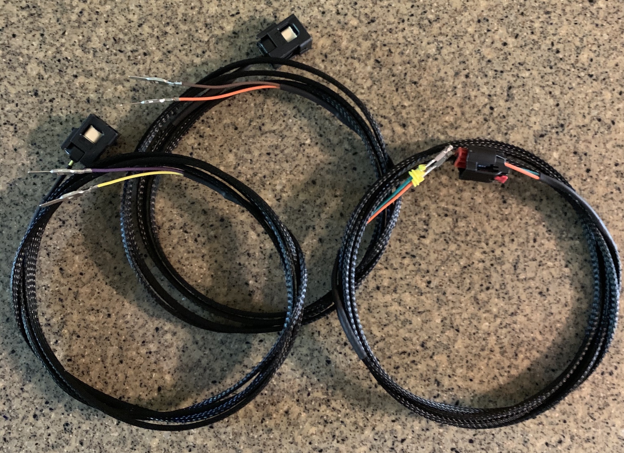
Post #8: DIY Harnesses
Post #9: How-to for the HD trucks
Post #10: HD install continued

The following lists out what you will need to get this accomplished on a 1500. The HD trucks utilize a one piece handle and already have the wiring in place for the rear antenna. Specific part numbers are listed in post #7, and I will update the list with additional items as needed.

Factory PE Parts
- Door handles for proximity entry x2 (handles are the same on both sides on the 1500)
- Door Handle Cap, Right (specific to each side and passive entry as there is a magnet inside)
- Door Handle Cap, Left (specific to each side and passive entry as there is a magnet inside)
- Front Door Wiring, Right (must support passive entry, or you can just add the 2 wires needed utilizing info in this thread)
- Front Door Wiring, Left (must support passive entry, or you can just add the 2 wires needed utilizing info in this thread)
- Rear bumper passive entry antenna (The cheaper $8 antenna has been proven to work)
- Rear Bumper wiring harness (must support passive entry, or you can just add the 2 wires needed utilizing info in this thread)

AlfaOBD
- Android tablet or Windows PC
- AlfaOBD software for your tablet or PC
- OBD interface (MX/MX+ is used by many, but there are cheaper options that work)
- Security Gateway (SGW) bypass

Tools:
- Trim tools (not 100% necessary, but well worth it to not damage panels and/or clips. Plenty of options online or at most local parts stores)
- The elusive 10mm socket and your choice of ratchet/driver (a short extension will be handy also)
- 6mm socket for speakers (5mm for the HD)
- T20 torx for the HD panels
- T25 torx for the 1500 door handle cap (needs to be long enough to reach inside the hole in the door, about 4". May also be able to use a small flathead for this)
- T27 torx for the door latch
- Small flathead screwdriver (1/8)
- Needle nose pliers
- Tape (for holding up the window once it’s unbolted. Decide what you feel comfortable using)

Important note: Passive entry will function with the addition of just the driver’s side handle (only activating from that handle obviously) and the settings configured in the BCM. However, if you choose to not add all pieces, fobik safe will not function as intended and it will trigger fault codes in the RF Hub. This means that there is a slight chance you could induce a condition that would allow the fob to be locked in the vehicle and will not be alerted. If you install both handles, and the 5th antenna, everything functions as intended and you will get an alert should you accidentally leave a fob inside the cab and attempt to lock the doors.
 
Last edited:

MayhemMOORE

Ram Guru
Joined
Apr 6, 2020
Messages
572
Reaction score
502
HARDWARE INSTALLATION

Start by removing the small plastic covers behind the door handle(s) using a small flathead screwdriver or similar device. Behind those you will see a total of 3x 10mm bolts, 1 behind the top handle and 2 below the lower handle. Go ahead and remove those and put them somewhere for safekeeping. Using a trim tool, remove the window switch by carefully prying it up and out of the door panel then disconnect it. Keep it nearby as you will need it shortly to lower the window.

Before you start removing the panel, grab a bucket or something to set it on once the clips are undone, or have a pair of needle nose in arms reach so you don’t have to leave the panel hanging by a cable to go get one. The easiest way to do get the door panel off is to use a little brute force rather than trying to work a trim tool around the entire panel to each clip. Keep in mind that door panel is actually 2 pieces (upper/lower) and if you get too crazy, you could break them apart. If you are uneasy about yanking on the panel, then proceed with working your way around to each clip with a tool.

If you choose to try the method of just pulling the panel off, grab ahold of the map pocket with one hand, or get in behind the corner of the panel with your fingers, while using your other hand to hold the actual door itself. Give the panel a good sharp tug and it should pop some of the clips loose. They are in there pretty snug, and it will make a lot of noise when it pops off, but you should be able to do it without breaking anything. Work your way around to release all the remaining clips. There are a few clips along the very top which can be tricky to get, but you can slide your hand back in there and work them loose. If you happen to break any of them, check the parts list for replacements. You may get a couple that don’t separate and come out of the door altogether. If that happens, just get them apart and put the halves that belong in the sheet metal back in before assembly.

Once the door panel is loose, there are some things connected to the backside you need to disconnect. The lock button should pull out pretty easily if it didn’t when the panel popped loose, but the cable to the handle can be a bit tricky. There are 2 small tabs which hold the end of the cable housing in the hole that you will need to pinch, use a pair of needle nose pliers, then slide the housing back through the hole. You can then rotate the cable out 90° and remove the end from the handle. If you have any additional wiring connected to the back of the panel, go ahead and disconnect it. That should free up the door panel and you can set it somewhere safely out of the way.

handle cable (1).jpeg

You should now be looking at the door carrier plate and be able to see most of the harness, the speaker, door module, etc… Make note of the one bolt around the edge that is missing. That’s because it’s the one from behind the door handle. This way you don’t spend 10 min crawling around like I did thinking you lost a bolt when you go to put it back together. Also, don’t put it back in before putting the door panel back on, or you’ll be pulling it off again.

IMG_7830.jpeg

Disconnect the wiring going from the door module up to the mirror now and secure it out of the way.

You will see two rubber plugs down by the bottom which are where you will access the bolts that hold the window to the regulator assembly. Pop them open so you can see in, plug the window switch back in and lower the window until the bolts are visible. Disconnect the window switch and set it aside for now. Loosen the two bolts and disconnect the window from the regulator. Carefully lift the window all the way up and secure it using tape or a wedge. If you have tint on your windows, DO NOT use tape on the inside or you risk damaging it. With enough tape on the outside going up and over the top of the door frame, the window should stay in place.

window port.jpeg

Where the door and body harnesses connect you will need to release some tabs under the rubber boot to free it from the body of the truck. The pic below shows the top tab released. A few people have said it is easier to release the bottom tabs first, so try both ways if one is giving you trouble. You may be able to work the boot back and get a view of the tabs, but if you just slide a thin screwdriver or something similar in between the boot and the sheet metal you should be able to get the tabs to release while wiggling the door connector. Be careful not to scratch up the paint. Just look on the new harness and you will see exactly where you need to press to release it from the body. Once released, you can unplug the connectors, and then feed the door harness through the door so will be ready to come out with the carrier plate.

IMG_7834.jpeg

To remove the door handle, locate the small black plug on the back of the door (latch side). Remove it, and then using the T25 torx, or a small screwdriver, begin to turn the screw counter clockwise.

cap screw.jpg

As you turn it, hold the handle cap and pull on it lightly while moving it back and forth. As you continue to turn the screw, you will feel the cap get looser, once it comes off, stop turning the screw, you are not trying to remove it.

cap out.jpg

To remove the handle itself, grasp it and slide it towards the rear of the door. Once it has slid to the rear, pull out at the back and the handle will pivot out and remove.

IMG_7823.jpg


On the driver’s side handle cap, you will need to remove the lock mechanism and install it in the new cap prior to reassembly.
 
Last edited:

MayhemMOORE

Ram Guru
Joined
Apr 6, 2020
Messages
572
Reaction score
502
There are 2 different ways to proceed from here, so review them both and decide which you prefer.

The first requires you to remove the 2 bolts hidden inside that connect the carrier plate to the latch assembly. The way I did it was to remove the speaker and reach in through the speaker opening to remove the 2 bolts. They are located towards the left side of the plate, directly behind the 2 things that look like a + with a circle in the middle. After that is done, remove the bolts around the edge of the carrier plate and set them aside. You should be able to pull back the carrier plate and disconnect the remaining wiring. Having a second set of hands, or a bucket to set the plate on helps when trying to disconnect the wiring going to the latch. Be careful when pulling the panel back, as there are some tabs that clip on to the metal door frame, so if it seems stuck, don’t just yank or you might break it. Once it’s all free, go ahead and remove the old harness from the plate and install the new one. You will have to route the wire around the outside of the window track and latch assembly which can be pretty tricky as there isn't much room to work. There are clips to hold the wire in place which you can see in the photo further down. Failure to properly route the wire could lead the the window jamming up on it or breaking it, so take your time and be careful. Make sure you feed the connector through the hole on the outside so you can plug the new handle in.

The second way is how the service manual shows you to do it.
@Meadz provided some details and the photos of the whole assembly removed for this method. Start by removing the 3 torx screws that connect the door latch assembly to the door itself. Next, loosen, but do not remove the torx screw on the outside of the door behind the door handle. You can then push the screw forward and the assembly will slightly fall into the door. Now you can remove the bolts from around the edge of the carrier plate and the entire assy including the door latch mechanism and exterior handle assembly should be able to come out as one unit. With this way it's easier to run the wires to the handles and clip them in, just don't forget to leave about an inch of slack and push the connector out through the exterior handle bracket as you reinstall everything.

Full carrier plate assembly removed:

20201117_210434.jpg

In these photos you can see the entire latch assembly and bracket behind the handle is still attached to the carrier plate, along with the cable that goes to the inside handle mechanism.

20201117_210501.jpg 20201117_210448.jpg

In the photo below you can see the new wiring for the PE handle in place, as well as the one torx screw that was loosened behind where the handle mounts.

20201117_210712.jpg

Install everything in reverse order from what you just did.

Now that all that is done, it's on to the easy part...
 
Last edited:

MayhemMOORE

Ram Guru
Joined
Apr 6, 2020
Messages
572
Reaction score
502
Configuring the BCM for passive entry with AlfaOBD.

Grab your SGW bypass and locate the Security Gateway. If you are unfamiliar with its location, it is located up inside the driver’s side footwell, behind where the headlight/parking brake switches are. The below pic shows the module, looking directly up from the floor. It's the black box with 2 connections on it, located right by the green and white star connectors.

*From what I have read, the bypass on the HD's is located behind the instrument panel and is a little more involved to access. Once I can confirm this and possibly get a photo of its location I will update this.

SGW Module.jpg

Release the connectors from the gateway and plug them into your bypass. That’s all there is to it.

Next, plug your OBD interface into the OBD port, which is located on the bottom edge of panel under the steering column. You should have no issues locating it, as it’s the only exposed connector in that area and will match up with your interface. If you haven’t done so already, set up your OBD interface with your tablet or computer via a Bluetooth or wireless connection.

With your foot off the brake pedal, press the Start/Stop button on the truck 2 times to place the ignition in to “Run”. Do not start the truck, just cycle the ignition to the “Run” position.

Once that is done, we are ready to make the changes in AlfaOBD. I opted not to include photos here since if you follow the steps one at a time you should have no issues. I do have screenshots, so if you need a visual to go along, I can get them added in.

Open up the app on your device and you should see the home screen.

To begin, click on the Bluetooth or Wi-Fi icon and connect to your OBD interface.

Once connected, select the Dodge/Ram icon.

On the first drop down menu choose your vehicle model.

On the 2nd drop down select “Body Computer”.

On the 3rd drop down you will need to select the appropriate BCM for your vehicle. For my 2020 I chose the very last one in the list.

The app should advance to a new screen where you can connect to the body computer. Once connected, it’s time to get in to making the changes needed.

Select the little icon in the bottom right that looks like a car with the hood open.

Select the drop down menu and go all the way to the bottom and select “Car configuration change”.

You should now have 2 additional drop downs below the top one. The top one will still say Car configuration change, and we aren’t going to mess with that one anymore. The next one down, the middle one, is where you are going to begin selecting the items to change.

Take your time and be sure you select the correct one each time as you proceed. To keep things simple, just start at the top and go down the list below, enabling and/or verifying each item as you go.

After selecting a setting to change in the middle drop-down, you will then select the command using the bottom menu. Reference the list below and make your selection based off the setting in bold.

After selecting the command in the bottom menu, hit “start”. The app will first verify the vehicle setting and give you a message indicating its current set state. If its current state is not set to what it shows in bold in the list below, press “start” again and this will make the change. You should get some text at the bottom saying the procedure was completed, however it did not always come up for me. If it doesn’t say it was completed, just hit start again and it will check the current status and tell you what it is. If it’s correct, move on to the next one.

The following list is all the settings you need to change or verify to enable Passive Entry. Each setting name is given, followed by the state it needs to be set to in bold. I made all the changes sequentially without cycling the ignition at all in between and everything worked just fine. Take your time as the full list in the app is long and you can easily scroll past a setting, especially the wireless ones as there are only a few. (The newer version of AlfaOBD allows you to search for a specific setting, so you can begin typing in the search bar and it will start narrowing down the list if you don't want to scroll through everything. Just make sure you keep track of the ones you change as you move down the list)

PASSIVE ENTRY BCM SETTINGS

VehConfig 3 fobik safe enable- YES

VehConfig 3 passive entry present- YES

LIN and Misc fobik safe alert no reply- YES

LIN and Misc fobik safe alert on system fault- YES

LIN and Misc fobik safe alert on search timeout- YES

LIN and Misc fobik safe alert per ignition cycle counter- 2

Wireless AP1 Left front- SMART SWITCH

Wireless AP2 Right front- SMART SWITCH

CustSetMenu 1 passive entry CSM present- YES

Cust.Prog.Features- Passive Entry Unlock All Doors or Approach Door- ENABLED


IMPORTANT NOTE:
With the configuration set as above, if you do not have all the hardware installed (such as the 5th antenna) fobiksafe will not operate as designed and there will be fault codes stored in the rfhub. If you utilize the inside lock button to lock the doors as you exit, whether or not the fob is inside, you will get an alert from fobiksafe and the locks will auto-unlock after closing. There is the small chance you could lock your fob in the truck if you ignore the warning since it doesn't actually know whether the fob is inside or not, and on the 3rd attempt the doors will remain locked. Once everything required for PE is installed, the whole system will function as intended from the factory…alerting you only if it senses a fob left inside the truck so you do not lock yourself out.

Once all the settings have been made you can cycle the ignition back to off. You can also remove the SGW bypass and OBD interface now.

Go ahead and disconnect the battery and let it sit for a bit. Anywhere from 15-30 min should be sufficient. The intent is to ensure the RF Hub re-reads and picks up on the new BCM configuration the next ignition cycle. (Although this may not be totally necessary, it isn't going to hurt anything)

This was initially completed on my '20 Bighorn which had the 8.4 non-nav unit. If you have nav, it may take a bit longer to show up in Uconnect, so don’t freak out if it isn't there right away. Give it a few ignition cycles and everything should show up. The actual passive entry will likely function even before the setting shows up in the menu. You will be able to find the passive entry option in settings, under “doors and locks" on your screen.

If you plan on adding the antenna and wiring to the rear of the truck, refer to the post that pertains to your specific model year.
 
Last edited:

MayhemMOORE

Ram Guru
Joined
Apr 6, 2020
Messages
572
Reaction score
502
2019 & 2020 Rear Antenna Install

This will help guide you through the basic process of adding the rear antenna to a 2019-2020 5TH-Gen 1500. Whether you use your own wiring, or replace the entire rear fascia harness, the antenna location will be the same. If using the factory harness, it’s going to be plug and play so just remove and replace the entire thing. If you’re just adding the 2 wires needed, then follow the steps below.

To add the two wires and connector for the rear antenna, start by finding the connector below, which is where the rear fascia connector plugs in to the body harness. It's right above the rear resonator on the driver's side.

IMG_7814.jpg

To unplug it, pull up on the little yellow tab and then the red piece will slide out. If the connector doesn’t pop off, you haven't pulled the red piece out enough. It will disengage on its own once you slide it out far enough.

Once unplugged, remove the first couple of clips from the frame so you have some slack, then remove the black cover from the backside of the rear fascia connector. You should be looking at something like this, and we will be working with terminal positions 19 and 20. Position 19 is the "PASSIVE ENTRY ANTENNA 5 SIGNAL" and position 20 is the "PASSIVE ENTRY ANTENNA 5 RETURN". Refer to the photo at the end of this post which shows the antenna connector and which wire is which.

IMG_7804 2.jpg

There will probably be little plugs in the terminal positions, so you need to push them out. If you have a tool for depinning connectors, slide it in the terminal positions from the face side of the connector (photo directly below) and the plugs will push right out. If you do not have one, a small piece of wire or a paperclip will likely work just as well.

IMG_7803 2.jpg

Once the plugs are out, before you can insert the terminals from your new harness, there is a plate that needs to be slid out of the way. In the photo below you can see it slid out of the connector, to the opposite side of the one you moved to unplug it. A small flathead should be all you need to get it started and then just slide it out far enough to access the positions you need.

IMG_7808 2.jpg

After that you can insert the new terminals into the backside of the connector. Don't force them in, they should go in with very little effort if they are oriented correctly. You will hear them click into place when they are seated. Once they're both in, slide the red tray back in.

You can then install the black cover on the back of the connector, and route your wiring however you choose over to the antenna. I ran the new harness inside the first section of wire loom so that it was contained in the black cover like all the rest, then I taped it all up and just ran the wires alongside the factory harness.

The photo below shows where the antenna mounts in a little cubby behind the center of the rear bumper. If you look up from under the truck, between the spare tire and bumper you will see it. If you drop the spare down you will have room to work and come up with a way of securing it with clips or small bolts.

IMG_7813.jpg
WgGXabF.jpeg
 
Last edited:

MayhemMOORE

Ram Guru
Joined
Apr 6, 2020
Messages
572
Reaction score
502
2021 Rear Antenna Install

For the 2021 models, there is a new connector utilized for the rear fascia harness. The basic concept of adding wires to it is the same, however the process to do so is a little bit different.

Start by locating the connector, which is in the same location as the 19-20’s, but does not look the same. There is a connector that looks similar to the previous trucks in the general location, but this is for the tail light jumper harness and is not what we are looking for.

ConnectorLoc.jpg

It may be helpful to remove the connector from the bracket it is clipped to so you can get a little slack and be able to see the release mechanism a little better. I also advise undoing the first clip which retains the harness to the side of the trailer hitch, this will allow you to sit comfortably behind the truck and work on it once it’s unplugged.

Once you are ready to disconnect the harness, refer to the photo below and follow the steps indicated. First, slide the red tab towards the rear. It should only move about ¼” give or take. Next, depress and hold the small serrated black tab. Finally, lift up on the white locking bar which will pivot up and over the connector shell, releasing the fascia harness from the body harness.

RearFasciaDisconnect.jpg

Once the connector is free and you have room to work, the black cover needs to come off to gain access to the wire-insertion side of the connector. Use a small flathead and carefully lift the little tabs around the cover while working it apart. They are only thin plastic, so be careful.

CoverTabs.jpg

Once the cover is removed, you will be able to see the wire-insertion side of the connector. You will be looking for positions 33 and 34 as indicated in the photo below. Since this truck already has passive entry, it has the factory wiring in these positions. When you look at your connector you will see 2 orange plugs like the other vacant positions.

Pinout.jpg

Just like on the 19-20’s, the rubber plugs need to come out before your terminals go in. This is where the ’21 differs again. Looking at the face of the connector as shown below, you will see a small white peg protruding above the green plate. This is connected to the plate that locks the terminal pins into the housing. You will need to insert something small into the opening and slide the peg towards the black housing as indicated in the 2 photos below. It doesn’t move much, but you should feel and/or hear it click slightly once it moves, and also notice the gap on the outside of it goes away.

IMG_9101.jpg

LockPlateOpen.jpg

Once you have moved the locking plate over, use a de-pinning tool/small paperclip/piece of wire to push the rubber plugs out the other side of the two terminal positions you will be using (circled in red above).

After the plugs are out, simply insert the new pins into the correct position from the wire-insertion side of the connector. (see photo below) The wire from pin 1 on the antenna connector (signal) will go to pin 33 on the rear fascia connector, and the wire from pin 2 on the antenna connector (return) will go to pin 34 on the rear fascia connector. They should only go in one way and will click in place. So if they aren’t going in easily, don’t force them. The seals may be a tight fit, so a small dab of dielectric grease may help them slide in, or you may need to gently pull the pin in all the way from the face side of the connector.

IMG_9091.jpg

Once both are in all the way, you can slide the white peg back over to lock them in place. Then just reinstall everything in reverse order from how you took it out.

Mounting the antenna is the same as it is on the ’19-20 models. Just find a way to secure it in the small cubby on the inside of the bumper behind where the license plate mounts.
 
Last edited:

MayhemMOORE

Ram Guru
Joined
Apr 6, 2020
Messages
572
Reaction score
502
If you are going to use the numbers below to order parts, double check them as things can change over time, so it's going to be up to you to verify you're getting the correct part when ordering. If you find a mistake please let me know so I can correct it.

5th Gen 1500 Handle and Cap Part Numbers
These should work on any of the 2019 and newer 5th gen 1500 trucks. Harnesses are going to be more specific based on your options, or you can just add the 2 wires and plugs to your existing stuff and save a good bit of money.

COLORBODY COLOR HANDLE, L & RBODY COLOR/CHROME HANDLE L & RHANDLE CAP, LEFTHANDLE CAP, RIGHT
Bright White6CV64GW7AD6CV361W7AD6CV50GW7AC6CV52GW7AB
Ivory White6CV64KGZAD6CV361WDAD6CV50JWDAC6CV52JWDAB
Diamond Black Crystal6CV64KXJAD6CV361XJAD6CV50KXJAC6CV52KXJAB
Maximum Steel Metallic6CV64KARAD6CV361ARAD6CV50KARAC6CV52KARAB
Granite Crystal Metallic6CV64LAUAD6CV361AUAD6CV50LAUAC6CV52LAUAB
Billet Silver Metallic6CV64JSCAD6CV361SCAD6CV50JSCAC6CV52JSCAB
Patriot Blue Pearl6CV64RPXAD6CV361PXAD6CV50RPXAC6CV52RPXAB
Blue Streak Pearl6CV64KCLAD6CV361CLAD6CV50KCLAC6CV52KCLAB
Flame Red6CV64PR4AD6CV361R4AD6CV50PR4AC6CV52PR4AB
Olive Green6CV64KFPAD6CV361FPAD6CV50KFPAC6CV52KFPAB

Replacement Clips for the 1500 door panels
Door Interior Trim Panel Retainer (Yellow): 6510747AA
Door Interior Trim Panel Retainer (White): 6510359AA

HD Part Numbers
Thank you to @01Time for providing the more comprehensive list below for the HD trucks than I had originally posted.

COLORBODY COLOR, FRONT LEFTBODY COLOR, FRONT RIGHTBODY COLOR, REAR LEFTBODY COLOR, REAR RIGHTBODY COLOR/CHROME, FRONT LEFTBODY COLOR/CHROME, FRONT RIGHTBODY COLOR/CHROME, REAR LEFTBODY COLOR/CHROME, REAR RIGHT
BILLET SILVER METALLIC1UJ81JSCAI1UJ86JSCAI1GH19JSCAF1GH18JSCAF6NV571SCAD6NV561SCAC6NV591SCAC6NV581SCAC
BLACK FOREST GREEN PEARL1UJ81KGZAI1UJ86KGZAI1GH19KGZAF1GH18KGZAF6NV571GZAD6NV561GZAC6NV591GZAC6NV581GZAC
BLUE STREAK PEARL1UJ81KCLAI1UJ86KCLAI1GH19KCLAF1GH18KCLAF6NV571CLAD6NV561CLAC6NV591CLAC6NV581CLAC
BRIGHT SILVER METALLIC1UJ81WS2AI1UJ86WS2AI1GH19WS2AF1GH18WS2AF6NV571S2AD6NV561S2AC6NV591S2AC6NV581S2AC
BRIGHT WHITE1UJ81GW7AI1UJ86GW7AI1GH19GW7AF1GH18GW7AF6NV571W7AD6NV561W7AC6NV591W7AC6NV581W7AC
BRILLIANT BLACK PEARL1UJ81AXRAI1UJ86AXRAI1GH19AXRAF1GH18AXRAF6NV571XRAD6NV561XRAC6NV591XRAC6NV581XRAC
DELMONICO RED1UJ81NRVAI1UJ86NRVAI1GH19NRVAF1GH18NRVAF6NV571RVAD6NV561RVAC6NV591RVAC6NV581RVAC
DIAMOND BLACK CRYSTAL PEARL1UJ81KXJAI1UJ86KXJAI1GH19KXJAF1GH18KXJAF6NV571XJAD6NV561XJAC6NV591XJAC6NV581XJAC
FLAME RED1UJ81PR4AI1UJ86PR4AI1GH19PR4AF1GH18PR4AF6NV571R4AD6NV561R4AC6NV591R4AC6NV581R4AC
GRANITE CRYSTAL METALLIC1UJ81LAUAI1UJ86LAUAI1GH19LAUAF1GH18LAUAF6NV571AUAD6NV561AUAC6NV591AUAC6NV581AUAC
MAXIMUM STEEL METALLIC1UJ81KARAI1UJ86KARAI1GH19KARAF1GH18KARAF6NV571ARAD6NV561ARAC6NV591ARAC6NV581ARAC
PATRIOT BLUE PEARL1UJ81RPXAI1UJ86RPXAI1GH19RPXAF1GH18RPXAF6NV571PXAD6NV561PXAC6NV591PXAC6NV581PXAC
PEARL WHITE1UJ81PWQAI1UJ86PWQAI1GH19PWQAF1GH18PWQAF6NV571WQAD6NV561WQAC6NV591WQAC6NV581WQAC
TRUE BLUE PEARL1UJ81KBUAI1UJ86KBUAI1GH19KBUAF1GH18KBUAF6NV571BUAD6NV561BUAC6NV591BUAC6NV581BUAC
WALNUT BROWN METALLIC1UJ81RUWAI1UJ86RUWAI1GH19RUWAF1GH18RUWAF6NV571UWAD6NV561UWAC6NV591UWAC6NV581UWAC
HYDRO BLUE METALLIC1GH19MBJAF1GH18MBJAF6NV571BJAD6NV561BJAC
OLIVE GREEN METALLIC1GH19KFPAF1GH18KFPAF6NV571FPAD6NV561FPAC


The following is a breakdown of the parts you will need to assemble your own 2-wire harnesses for the doors, as well as the rear antenna. All of the connectors and terminals can be found at Mouser or Digikey, except for the Yazaki stuff.

Rear Antenna Wiring Parts
22AWG wire (2 colors to make it easy)
Heat shrink tubing (recommended)
Braided wire sleeve (recommended)
Rear PE Antenna: 52112204AA or 56046957AA should work in this location
2019 & 2020 Rear Fascia Connector Terminals: TE Connectivity 1241380-1
2019 & 2020 Rear Fascia Connector Wire Seals: TE Connectivity 828904-1
2021 Rear Fascia Connector Terminals:
2021 Rear Fascia Connector Wire Seals:
2019+ Rear Antenna Connector Shell: TE Connectivity 1-1438608-5
2019+ Rear Antenna Connector Shell Terminals: TE Connectivity 1355717-1
2019+ Wire Seals for Antenna Terminals: TE Connectivity 963530-1

Door Handle Wiring Parts
18AWG wire (2 colors to make it easy)
Heat shrink tubing (recommended)
Braided wire sleeve (recommended)
Door Connector Terminals: Aptiv 10762775
Door Handle Connector Shell: Yazaki 7283-6079-30
Door Handle Connector Shell Terminals: Yazaki 7116-4720-02

Yazaki parts are hard to find without ordering minimum quantities. One option is to call SMD Inc, and see if they’ll send you free samples (2 connectors, 4 terminals).
 
Last edited:

MayhemMOORE

Ram Guru
Joined
Apr 6, 2020
Messages
572
Reaction score
502
For those that don’t want to buy the entire replacement door or bumper harnesses just to gain two wires and a connector in each location, you can use the same connectors and terminals FCA uses and add them to your existing harnesses just like factory. The following information will assist you in accomplishing the wiring. Thank you to @Jimmy07 for this great information. He has also offered to build these for people, and they are top-notch quality. Contact him if you would rather go that route in lieu of building them yourself.

Terminal and connector part numbers are all in post #7

To begin, below is the door harness route that shows how the door handle connector wires make their way to the door connector boot. You will be adding the connector and wiring that runs from the door-to-body connector on the right, over to the handle connector at the end of the white line, so make sure you use long enough wires.

Harness Routing.jpg

This is the pin-out of the driver and passenger side door handle connector:

EEBHM5O.jpg

This is the pin-out of the driver’s side door connector, and where to insert the two wires from the door handle:

D-Side .jpg

Driver's Side.jpg

This is the pin-out of the passenger side and where to insert the terminals in the door connector:

P-Side.jpg

Pass Side.jpg

Rear Antenna Harness

Below is location of the rear antenna connector and the pin-out to show which wire goes where. Be sure the wiring is long enough to reach between the two points:

P9nRTzT.jpg

WgGXabF.jpg
 
Last edited:

MayhemMOORE

Ram Guru
Joined
Apr 6, 2020
Messages
572
Reaction score
502
Thanks to @Scyllint, there is now some photos and info to help with anyone wanting to do this on the HD's.

HD install is similar to the 1500 but a few differences.

Remove 6 T20 torx plastic screws holding outer door panel in. Remove their bases also or they will fall out when you pull the panel.
plastic panel screws.jpg

Remove black plastic panel by mirror.

There is one Philips head screw behind the door handle holding that trim panel in.

interior handle and screw.jpg

After all the screws are out, pull up on the panel to remove it.

Note from member @Sako458Lott: Before completely removing the trim panel you will need to disconnect the window/door lock switch from the door. I found that is easier to unlock the plug by partially removing the switch (4 metal tabs you have to push in). You can than set the trim panel aside. I then fully removed the window switch and plugged it back in so I could align the window locking tabs with the access hole in the window track

The gray plastic square needs to be opened to access the left window release. The right window release is behind the speaker. Speaker screws are 5mm. This is basically the same as the 1500’s but the removal part is different. Unplug all the plugs, etc. (this may not be necessary, it is up to you how to proceed with unplugging everything) Take a picture of your power module so you know how the plugs go back in.

door panel.jpg

In this picture, my thumb is on the window where I’m going to lift up, while pushing on the 2 release tabs. One is to the right of my hand with a black dot of goo on it. The other is to the right of that, accessed through the slot in the metal window track.
window removal 1.jpg

This side gave me a little more trouble, but same idea. Try pulling up on the whole window from the top if it looks like the tabs have released but its not moving.
window removal behind speaker.jpg

Unplug the door harness. Its tight so wiggle it out carefully, move the door back and forth to give yourself some room. I found popping one release tab and working the rubber boot off made it a little easier to get the other tabs out.

Note from member @Sako458Lott: Before unplugging the door harness, I found it easier to unfasten the part of the harness attached to the front of the door (also makes it easier to feed the passive entry wire harness through it). Two T20 torx screws need to be removed - I used a 1/4" drive ratchet with T20 bit. This also makes it easier to remove the inner door panel since it needs to be shifted forward to clear the lock mechanism (be careful because it is held to the door panel by flimsy plastic. It does have some flex)

20201222_102755.jpg
door plug close up.jpg

Unscrew the 3 T30 torx screws holding the door latch in place.
20201222_095616.jpg

Reach in through the square access hole and unclip the latch rods from their holders. Just pop them out of the clip, rotate the plastic clips out of the way and pull the rod out of its hole.
20201220_111717.jpg

Remove the 10mm bolts holding the panel in and pull the whole thing off and carefully set aside. Lifting it up and out helps the door latch assembly clear the door.
20201222_095918.jpg
 
Last edited:

MayhemMOORE

Ram Guru
Joined
Apr 6, 2020
Messages
572
Reaction score
502
Remove the rods from the door handle and the 3 5/16 bolts. Remove the handle. Put in the new one and wire it up. Install in reverse order and follow the instructions for the 1500’s. AlphaOBD setup is exactly the same.
door handle bolts.jpg

door handle rods.jpg

Once you are ready to add the wiring into the factory connectors, refer to the images and diagrams below for where you will need to put them on each side. Don't forget that you need to release the white and brown face locks to be able to insert the new terminals all the way. There should be a little tab on each side you can gently lift to get them to release and allow you to insert the terminals (you can see one in the second photo).

MQDjLqP.jpg

insert like so.jpg

driver side.jpg

passenger side.jpg


Rear Antenna Install

This is the easiest part. Looking up from under the spare tire, on the left side is a plug with a dummy cap plugged into it. Plug your antenna in to this plug. That’s it!

20201221_111928.jpg

Either zip tie it up out of the way or find some kind of fasteners to mount to the factory holes. The dummy plug has a retainer clip plugged into one of the holes. I tapped 2 sheetrock anchors into the holes and screwed the antenna in with 2 sheetrock screws. Its not perfect but it is surprisingly stable. We’ll see how it holds up.

mounted 2.jpg
 
Last edited:

ssick92

Active Member
Joined
Jul 12, 2020
Messages
64
Reaction score
29
Amazing work! Thanks to all of you who helped figure this out, as I'm sure there are tons of us who will be attempting this mod in the near future! Got the parts ordered, only time will tell if I am able to make it work.

Figured I might as well copy over my part list that I ordered for my 2020 Granite Crystal Metallic from the other thread, although can't quite confirm they are all correct since they haven't been delivered yet. Don't blame me if they are wrong!

Part NumberDescriptionQty
52112204AAPassive Entry Antenna1
6CV64LAUAD Exterior Door Handle, Right (Body Color)2
6CV50LAUACDoor Handle Cap, Left1
6CV52LAUABDoor Handle Cap, Right1
 
Last edited:

z0n3

Ram Guru
Joined
Jun 16, 2019
Messages
1,722
Reaction score
1,371
Bravo to you and @Jimmy07 for figuring this out. This is going to make a lot of people happy. This here is the reason these forums exist. Thanks guys!
 

Jimmy07

Honorary Site Supporter
Site Supporter
Joined
Apr 11, 2019
Messages
1,993
Reaction score
2,170
If anybody doesn’t want to spend the money for the entire door harnesses and rear facia harness, and doesn’t feel like building the add on harnesses with the parts, let me know and I can build them for you-
Ybotwhi.jpg
 

dts828

Ram Guru
Joined
Dec 28, 2019
Messages
875
Reaction score
498
Location
Atlanta, GA
Has anyone thought of trying to splice in a rear handle to see if it work? Probably a long shot but the wiring diagram makes it appear the handle is just acting like a switch.

Would love to have rear door Passive entry because half the time I open my rear door first to put my computer bag in the back.


Sent from my GM1917 using Tapatalk
 

Jimmy07

Honorary Site Supporter
Site Supporter
Joined
Apr 11, 2019
Messages
1,993
Reaction score
2,170
Has anyone thought of trying to splice in a rear handle to see if it work? Probably a long shot but the wiring diagram makes it appear the handle is just acting like a switch.

Would love to have rear door Passive entry because half the time I open my rear door first to put my computer bag in the back.


Sent from my GM1917 using Tapatalk
Yes, that will work. Many have done it on the 4th gens.
 

MayhemMOORE

Ram Guru
Joined
Apr 6, 2020
Messages
572
Reaction score
502
Has anyone thought of trying to splice in a rear handle to see if it work? Probably a long shot but the wiring diagram makes it appear the handle is just acting like a switch.

Would love to have rear door Passive entry because half the time I open my rear door first to put my computer bag in the back.


Sent from my GM1917 using Tapatalk

I’ve thought about doing it as well. But I find it easy enough to just reach in the front handle as I walk up to unlock all the doors. May look into it down the road though.
 

dts828

Ram Guru
Joined
Dec 28, 2019
Messages
875
Reaction score
498
Location
Atlanta, GA
I’ve thought about doing it as well. But I find it easy enough to just reach in the front handle as I walk up to unlock all the doors. May look into it down the road though.
Yeah, that's what I do now. My last car had all 4 door so I'm a little spoiled. If I come across an extra handle I'll give it a try.

Sent from my GM1917 using Tapatalk
 

MayhemMOORE

Ram Guru
Joined
Apr 6, 2020
Messages
572
Reaction score
502
For anyone that orders the OEM parts and can confirm they work, if you PM me the part numbers, year and color of your truck, and any additional options you have from the factory in the doors, I will make one of the posts I have reserved dedicated to a list of confirmed part numbers for each color there is. This will help a lot of people out having a short list specific to each color rather than having to search it all.
 

Users who are viewing this thread

Site Vendors

https://www.jasonlewisautomotive.com/
Top