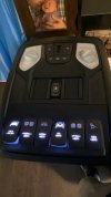
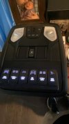
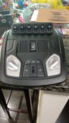
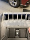
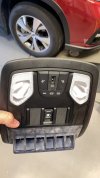
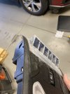
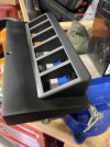
Got my panel installed this week and ran wires through pillar and headliner. I wish I had taken a picture of behind the switches. I did 2 molex plugs on mine, a 3 pin and a 6 pin. The 3 pin carries a ground, ambient light wire to light the letters on the switch when they are off and a main power wire for switch power in. Then the 6 pin carries all of the individual switch power outs. I have relays for the larger accesories but I ran a heavy enough (14ga) wire for power in to run smaller accessories on just switched power out if I want. For the screw and nut I used a small #6 floating clip nut and a normal 6-32 screw cut to length. I just popped the latch mechanism out for the sunglasses holder and slid the clip nut over the screw hole. Hope to have some more boxes show up this weekend to start hooking up things. The switches I anted to use are on backorder till october (white LED Otrattws) so I had to order their red ones and some 12v 5mm white LEDs and make them myself. I will say that after taking theirs apart and taking apart the CE Chinese ones apart to compare, the Chinese ones are built a lot better with a board and LED vs just a thin strand of copper wire to a spring soldered to the led in mine.

")