5thGenRams Forums

Register a free account today to become a member! Once signed in, you'll be able to participate on this site by adding your own topics and posts, as well as connect with other members through your own private inbox!

E-Torq battery benchtop troubleshooting

helloSir

New Member
Joined
Jun 25, 2022
Messages
2
Reaction score
0
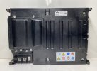
Recently I received a Ram 1500 E-TORQUE 48V Battery Pack Assembly 04610376AD I believe it is new (I buy damaged semi freight pallets) but wanted to yank out the battery for a project, but would like to know table top way to troubleshoot 48 to 12 volt DC DC converter. Mainly looking for a pin out on the 12 pin connector but any technical info on the battery would be helpful. I looked up in the Chilton database and didn't find any info on this model of truck and don't really feel like paying a subscription to view the truck wiring diagram for this project through a different vendor. I do feel a little bad ripping into it though since it is most likely a new module and will only be using a portion of it.
 

Attachments

  • s-l500.jpg
    s-l500.jpg
    26.3 KB · Views: 63

stevj

Well-Known Member
Joined
Aug 23, 2018
Messages
445
Reaction score
423
Location
On a clear day, I can see Seattle from my house.
Is this what you need?
Might be hard to read on account of Ram protection scheme for their schematics. See this post for info.
I bought their schematics, but they're near useless because it takes a 3rd party software to screen capture.
If you need beter resolution, I can try to get a clearer picture for you.
Steve
Battery.png
 
Last edited:

helloSir

New Member
Joined
Jun 25, 2022
Messages
2
Reaction score
0
Cool, yes that is what I was looking for I checked out pins 3&4 and 9&10 and read 120 ohms which seems about right for a CAN bus. I haven't tried it yet but am assuming B+ is the 12v system, and for the fused ignition and the fan control do you know if they are 12 v as well( I don't know how digital ram has taken their new trucks). Also I cant read the cooling fan supply pin, is it pin 6 or a pin 8.

As for the proprietary control over the schematics that really sucks, there is nothing novel about the wiring or design of the car for maintenance it is all common knowledge, even how the new hybrid systems are designed.
 

stevj

Well-Known Member
Joined
Aug 23, 2018
Messages
445
Reaction score
423
Location
On a clear day, I can see Seattle from my house.
You are correct. B+ is +12VDC from the engine compartment battery.
Pin 1. Fused B+ (12VDC) from 300amp fuse F202 in Engine Compt power center.
Pin 2. Fused B+ (12VDC) from 10amp fuse 50 in interior power center.
Pin 5. Chassis ground.
Pin 6 is not shown on this diagram.
Pin 8. Battery module cooling fan 12VDC from 20amp fuse 05 in interior power center. Active in RUN via relay on PCB in interior power center.
Pin 11. Fused Ignition Switch Output (Run - Start). 12VDC from 10amp fuse F35 in Engine Compt power center.
Hope this helps.

Steve
Maybe this one will be easier to read?
Capture.PNG
 
Last edited:

Jase

New Member
Joined
Dec 10, 2022
Messages
3
Reaction score
0
hi
sorry to dig up old thread
am struggling to 100% read screen capture if I read correct and as you say
Pin 1. Fused B+ (12VDC) from 300amp fuse F202 in Engine Compt power center
I cant see anything on schematic, do you know is there any e-torque circuitry involved or is this pin 1 direct to battery ??
id direct to battery am thinking I could use this as high current (50a) power supply behind rear seat (to charge an aux battery)

thanks
Jase
 

Users who are viewing this thread

Top