5thGenRams Forums

Register a free account today to become a member! Once signed in, you'll be able to participate on this site by adding your own topics and posts, as well as connect with other members through your own private inbox!

Code B1587 Antenna Short to Ground

OhioBigHorn

Active Member
Joined
Jan 13, 2021
Messages
86
Reaction score
25
Has had anyone had issues with their antenna having to be replaced. I have had my antenna replaced twice the second replacement lasted about 24 hours. Symptoms No AM/FM reception but satellite works. I did have the rear window wet headliner issue maybe that has something to do with it.

 

djevox

VP of Creative Thinking
Staff member
Site Supporter
Joined
Aug 27, 2021
Messages
4,209
Reaction score
4,578
Location
MD
Sounds like some part of an extension cable or a module is damaged, but this is something that would take habds-on troubleshooting and a bunch of spare time to figure out. Is the antenna all they replaced both times?
 

OhioBigHorn

Active Member
Joined
Jan 13, 2021
Messages
86
Reaction score
25
Yes antenna only. Dealer tech really hasn't done much trouble shooting just goes right in and swaps antenna's
 

djevox

VP of Creative Thinking
Staff member
Site Supporter
Joined
Aug 27, 2021
Messages
4,209
Reaction score
4,578
Location
MD
That’s not good. It may be worth taking both your receipts, present them to the service manager, and tell them they’re not being paid to guess and they need to do actual troubleshooting. Maybe in a more diplomatic manner though.
 

OhioBigHorn

Active Member
Joined
Jan 13, 2021
Messages
86
Reaction score
25
Yeah I will. Goes in next week. Planning on kindly asking for a different tech.
 

kapinallinen2

5thGenRams Supporter
Site Supporter
Joined
Jan 16, 2019
Messages
1,640
Reaction score
1,175
Location
Southern Maryland.
B1587? Does not seem a valid code.
B1578 is a different story. If so, there is a lengthy troubleshooting procedure.
Possible causes are:

BAD ANTENNA CONNECTION
AUDIO ANTENNA CIRCUIT
AUDIO ANTENNA
RADIO
 
Last edited:

OhioBigHorn

Active Member
Joined
Jan 13, 2021
Messages
86
Reaction score
25
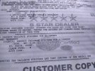
This is what they gave me.
 

Attachments

  • IMG_20230202_190027740_HDR.jpg
    IMG_20230202_190027740_HDR.jpg
    224.9 KB · Views: 17

OhioBigHorn

Active Member
Joined
Jan 13, 2021
Messages
86
Reaction score
25
B1587? Does not seem a valid code.
B1578 is a different story. If so, there is a lengthy troubleshooting procedure.
Possible causes are:

BAD ANTENNA CONNECTION
AUDIO ANTENNA CIRCUIT
AUDIO ANTENNA
RADIO
Maybe they typed it in wrong
 

kapinallinen2

5thGenRams Supporter
Site Supporter
Joined
Jan 16, 2019
Messages
1,640
Reaction score
1,175
Location
Southern Maryland.

Theory of Operation​


The Radio is provided with a fused Battery and Ground circuit. When the Ignition is turned on, the Security Gateway Module (SGW) transmits a wake up signal over the CAN bus to the Radio. The Radio monitors the Speaker, Antenna and Microphone circuits for faults.


The Radio manages the hands-free, navigation, and satellite functions of the vehicle. The Radio becomes operational after receiving a wake up signal over the CAN-IHS data bus indicating the status of the ignition switch is On. Depending upon audio system options, the Radio can play audio from many different media sources, such as the 3.5 millimeter auxiliary (AUX) port, a universal serial bus (USB) port or through wireless Bluetooth™ audio streaming. The Radio is capable of using AM/FM, Cellular, Global Positioning System (GPS) and Satellite Radio signals depending upon the audio system/vehicle configuration.


Make sure any serviced speakers are similar to the one being removed. The Radio uses the vehicle build configuration data (based upon sales code) to determine the audio configuration.


For additional information regarding the description and operation of the Audio System. (Refer to 08 - Electrical/8A - Audio/Video/Entertainment/Connectivity/Description) and (Refer to 08 - Electrical/8E - Electronic Control Modules/RADIO/Description) .


When Monitored and Set Conditions​


When Monitored:


  • If the ignition is on.
  • If battery voltage is within 9 V and 16 V.

Set Conditions:


  • If the Radio detects voltage sensed on the antenna is of 0 V.

Default Actions:


  • No reception on AM/FM signal.


Possible Causes​

BAD ANTENNA CONNECTION
AUDIO ANTENNA CIRCUIT
AUDIO ANTENNA
RADIO

Always perform the PRE-DIAGNOSTIC TROUBLESHOOTING PROCEDURE before proceeding. (Refer to 28 - DTC-Based Diagnostics/Standard Procedure)


Diagnostic Test​


1. READ AND RECORD DTCS AND ENVIRONMENTAL DATA - ERASE DTCS AND CHECK FOR DTC TO RETURN


  1. With the scan tool, read DTCs in all Electronic Control Units (ECUs) and record on the repair order.

  1. With the scan tool, run a vehicle Scan Report, or record the Environmental Data related to the DTCs.

  1. NOTE: A front door must remain open whenever checking or erasing Radio DTCs.

  1. With the scan tool, perform an ECU reset to the Radio, and then erase DTCs.

  1. Turn the ignition off for a minimum of 10.0 seconds.

  1. Turn the ignition on.

  1. Turn the Radio on and set the volume to 25.

  1. Adjust the speakers to the front and center.

  1. With the scan tool, read the active Radio DTCs.

NOTE: A front door must remain open whenever checking or erasing Radio DTCs.

Did the DTC return?

Yes

  • Go To 2

No


2. ANTENNA INSPECTION


  1. Using Service Information locate and verify the antenna is on the vehicle.

  1. Visually inspect the Antenna for damage.


Is the antenna missing or damaged?

Yes


No

  • Go To 3


3. CHECK THE ANTENNA CONNECTIONS


  1. Turn the ignition off.

  1. Disconnect the Radio Antenna connector at the Antenna.

  1. Disconnect the Radio Antenna connector at the rear of the Radio.

  1. Inspect both of the Radio Antenna connections and verify the Antenna is torqued to specification.


Were the antenna connections clean and torqued to specification?

Yes

  • Go To 4

No


4. TEST THE ANTENNA CABLE


  1. Disconnect the Antenna cable at the base.

  1. Connect the appropriate Adapter 9977-6-1 or Adapter 9977-6-3 to the Antenna cable at the back of the Radio.

  1. Connect the appropriate Jumper 9977-6-4 or Jumper 9977-6-2 to the Antenna cable at the Antenna base.

  1. Measure the Resistance across the tool terminals.


Is the resistance above 52.5 Ohms?

Yes


No

  • Go To 5


5. CHECK THE AUDIO ANTENNA


NOTE: Antenna reception testing must be done outside and away from man made structures or natural features to ensure all signals are not obstructed.
  1. Turn the ignition off.

  1. Replace the audio antenna for a faultless one (replacement for test).

  1. Turn the ignition on.

  1. With the scan tool, perform an ECU reset to the Radio, and then erase DTCs.

  1. Turn the ignition off for a minimum of 10.0 seconds.

  1. Turn the ignition on.

  1. Operate the vehicle in the conditions that set this DTC.

  1. With the scan tool, read DTCs from the Radio.


Did the DTC return?

Yes


No


6. CHECK RELATED HARNESS CONNECTIONS


  1. Disconnect all Radio harness connectors.

  1. Disconnect all related in-line harness connections (if equipped).

  1. Disconnect the related component harness connectors.

  1. Inspect harness connectors, component connectors, and all male and female terminals for the following conditions:
    • Proper connector installation.
    • Damaged connector locks.
    • Corrosion.
    • Other signs of water intrusion.
    • Weather seal damage (if equipped).
    • Bent terminals.
    • Overheating due to a poor connection (terminal may be discolored due to excessive current draw).
    • Presence of foreign conductive materials on connector pins and terminals.
    • Terminals that have been pushed back into the connector cavity.
    • Perform a terminal drag test on each connector terminal to verify proper terminal tension.

    Repair any conditions that are found.

  1. Reconnect all Radio harness connectors. Be certain that all harness connectors are fully seated and the connector locks are fully engaged.

  1. Reconnect all in-line harness connectors (if equipped). Be certain that all connectors are fully seated and the connector locks are fully engaged.

  1. Reconnect all related component harness connectors. Be certain that all connectors are fully seated and the connector locks are fully engaged.

  1. Turn the ignition on.

  1. With the scan tool, perform an ECU reset to the Radio, and then erase DTCs.

  1. Turn the ignition off for a minimum of 10.0 seconds.

  1. Turn the ignition on.

  1. Using the recorded Environmental Data, along with the When Monitored and Set Conditions above, operate the vehicle in the conditions that set the DTC.

  1. With the scan tool, read Radio DTCs.


Did the DTC return?

Yes


No


kapinallinen2

5thGenRams Supporter
Site Supporter
Joined
Jan 16, 2019
Messages
1,640
Reaction score
1,175
Location
Southern Maryland.
Yes it is, straight from the manual. Leave to Fiat LOL...
Actually, it has proper numbering in the manual, not sure why it looks like that here
edit: could be that 1=1, 1+1=2, 1+1+1=3 and so on.
:rolleyes:
 
Last edited:

kapinallinen2

5thGenRams Supporter
Site Supporter
Joined
Jan 16, 2019
Messages
1,640
Reaction score
1,175
Location
Southern Maryland.
A good possibility. Corrosion in a connector could cause low resistance to the ground, throwing a code.
 

OhioBigHorn

Active Member
Joined
Jan 13, 2021
Messages
86
Reaction score
25
Now on to my fourth antenna. The third one lasted less than 24 hours. Dealer says if it happens again the will get Chrysler involved
 

OhioBigHorn

Active Member
Joined
Jan 13, 2021
Messages
86
Reaction score
25
Four bad antennas in a row? something else is wrong.
Agreed. They hooked a "test antenna" to it and cleared the code and it worked fine so they replaced it and worked fine and sent me on my way again. I'm sure I will be calling them again soon.
 

Users who are viewing this thread

Top