5thGenRams Forums

Register a free account today to become a member! Once signed in, you'll be able to participate on this site by adding your own topics and posts, as well as connect with other members through your own private inbox!

Grounding auxiliary battery to chassis - Does it affect IBS?

jimothy

5thGenRams Supporter
Site Supporter
Joined
Dec 18, 2020
Messages
1,327
Reaction score
2,772
Points
113
Location
Atlanta, GA metro
I've added a battery box to the bed of my truck. This is to run a fridge, some lights, and a few other DC devices when camping.

Prior to this, I installed (and still have) light pods on my A-pillars. I want to be able to run these from the battery box so I can use them when stopped if I need some extra light, without worrying about draining the starting battery.

But sometimes, I don't want to lug that battery boxy around, so I came up with what I thought was an ingenious idea: Using Anderson SB50 connectors, I can plug a junction box into either the truck or the battery box. This worked well when I had both a positive and negative wire running from the junction box back to the engine bay, where the A-pillar light pods are connected. (The reason for running from the junction box back to the engine bay is because I want the option to run the pods from the battery box).

Then it occurred to me, there's no reason to run two lengths of wire (positive and negative), when I can simply ground the pods to the chassis; there are ground points on both sides of the engine bay, so this is easy to do.

That works fine when I've got the Anderson plug from the junction box plugged into the Anderson plug to the truck (run via 6 AWG wire). I was confused for longer than I should have when it no longer worked when connected to my battery box, until I said, duh, of course, I no longer have a circuit, because the light is grounded to the chassis, but the battery box is not.

So, just ground the battery box to the chassis too, right? Grounding a "house" battery appears to be common for RVs and trailers.

But, would doing so confuse the truck's IBS? Would the truck assume the power being consumed from my battery box (fridge, lights, etc.) is actually being drawn from the truck's battery? Likewise, my battery box is charged via solar; would the truck's IBS think it's receiving charge that it's not?

Likewise, I've got something akin to an IBS on the battery box (Victron SmartShunt). Like the IBS, it connects to the negative terminal on the battery, then the load's negative connects to the SmartShunt rather than the negative battery terminal. Would my SmartShunt think that power discharged from and charged to the starter battery is coming from my battery box?

Would both the truck and SmartShunt get a wrong picture of state of charge?

Photos coming...
 
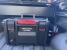
Here's my battery box. It's designed to be removable and portable, rather than mounted permanently in my truck bed.

In this photo, you can see a few things: On the right, two Anderson plugs entering the battery box. Grey is 12V and is going to a junction box mounted on my bed rack; the junction box contains fuses and a controller for my light pods.

The blue Anderson plug on the right is coming from the solar charge controller (the blue box mounted to the side of the bed). This delivers 24V, as the box contains a 24V 50Ah LiFePO4 battery. There's also a Anderson plug on the front of the box, which I can use to draw up to 50A @ 24V, and which I can also charge the battery via an AC-DC charger. Anyway, the two blue, 24V Anderson plugs aren't so relevant to this discussion of grounding the battery. (If you're not familiar with Anderson plugs, they are color coded so blue can only mate with blue, red with red; grey and black can mate with each other. This prevents me from accidentally plugging 24V and 12V together).

Not visible in this photo, as it is behind the battery box, is another Anderson plug. This is connected to 6 AWG wire: The positive wire runs to the truck's battery, and the negative is run the the truck's chassis. I can connect the junction box Anderson to it, and run my lights from the truck rather than my battery box.

In this photo, the battery box is connected to the junction box via the grey Anderson. Both the positive and negative wires run to the junction box via 10 AWG wire (I'm dealing with max 30A and a shorter distance, so 10 AWG is sufficient). There is currently connection to the chassis here, which is why lights connected to the junction box work but my A-pillar pods, grounded to the chassis, do not.

More to come...

tempImageCKVbrW.jpg
 
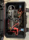
Here you can see what's inside the battery box. A 24V LiFePO4 battery, two fuse boxes (one for 12V, one for 24V), a circuit breaker, positive terminal fuse, a buck converter to go from 24V to regulated 13.8V, and, on the negative battery terminal, the Victron SmartShunt.

The SmartShunt works similarly to the truck's IBS: It monitors the battery and reports its state of charge (it also, incidentally, monitors the battery's temperature, and tells the solar charge controller to stop charging below freezing, as that would destroy a lithium battery. The thin red and black wires are for monitoring the battery's voltage and temperature).

tempImageNKYtZV.jpg
 
The way I would ground the aux battery to the chassis—if that's the right thing to do—is via the Anderson cable that runs to the junction box. The positive wire would continue to run directly to the junction box. The negative wire, however, would run to the chassis. Then another negative wire would run from the chassis to the junction box.

To sum up, my questions are:

  1. Is it safe to ground the battery box in this way? I'm pretty sure the answer is yes, but if I'm wrong, I'd like to know.
  2. Would the truck's IBS get confused by additional current running through the chassis? If so, what are the consequences of such confusion? As long as it doesn't damage the starter battery, alternator, or other electronics (e.g., because it thinks more power is being drawn than actually is so it runs the alternator higher to recharge it, or overcharges the starter battery)
  3. Would the aux battery's SmartShunt likewise get confused? This I'm less worried about. The solar charge controller relies on the battery's voltage, not reported state-of-charge (SOC), to decide the optimal charging voltage and current, and when to stop charging. So worst case, I figure, is the SOC would be inaccurate.
  4. Is there a better way to do this than I proposed?
I'm leaving on a two-week "overlanding-ish" trip, which is the motivation for this setup. Running a negative wire back to the A-pillar lights is an option if I can't figure this out in time. It would solve the immediate problem, and I can sort out the rest when I return.
 
Not unless you connect to the battery directly bypassing the stupid sensor on the negative terminal. Run your connections to in front of it if you want the load monitored.
 
I would put one of these in the circuit Smart Start SBI 12V 100A Eliminates the concern about power usage.
I don’t think I need an isolator for my setup. That would be needed if I connected the batteries in parallel; starter positive to aux positive, starter negative to aux negative. By sharing the chassis ground, negatives are effectively connected, but positives are not. The Redarc manual calls for connecting the SBI to the positive terminals of both batteries.

(Note too that connecting the two barreries in parallel is not an option, as the aux battery is 24V. I would need a DC-DC charger if I wanted to charge the aux battery from the starter battery/alternator).

It occurred to me that I can answer at least one of my questions with a simple test. Ground the aux battery as I described, then with nothing supplying current to or drawing current from the aux battery, monitor what the SmartShunt reports for the aux battery.

It should be zero or close to it. If the SmartShunt reports a positive number for current, it thinks (incorrectly) that the aux battery is receiving a net charge. A negative number indicates the shunt thinks current is being drawn from the aux battery.

I’d do this test with the engine running, then with the truck ignition in the aux position with headlights on to draw current from the starter battery. If the SmartShunt reports non-zero current, then it’s confused because of the common ground. If it reports zero, then there’s no confusion.

Further, if the SmartShunt isn’t confused, I can reasonably conclude that the IBS also won’t be confused, since they perform a similar role. A zero reading ought to mean neither battery monitor “sees” the current draw on the other battery.

I will test this idea in the afternoon and report back.

Thanks , and I apologize for the wordiness of my posts.
 
Not unless you connect to the battery directly bypassing the stupid sensor on the negative terminal. Run your connections to in front of it if you want the load monitored.
The chassis ground is connected to the monitored side of the IBS (that is, not directly to the negative terminal of the starter), so that’s not a worry.

But that’s also kind of the opposite of the scenario I’m concerned about. The loads (fridge, LED pods, and a few other DC devices) aren’t drawing from the starter battery, and I don’t want the IBS to “see” their current and think that there is addition current draw. I want current from these loads to be unseen by the IBS, as they are being drawn from the aux battery in the truck bed, rather than the starter.

So one option would be to ground the aux load directly to the starter battery negative, purposely bypassing the IBS. That’s probably a bad idea for a number of reasons, but it would also be pointless. The reason for wanting to ground to the chassis is so I don’t have to run a negative wire from the aux battery in the bed to the front of the truck, where one pair of aux light pods are.
 
A shared ground shouldn't be a problem if the load is provided from a separate supply, there's no draw it can sense. Just make sure that you have a diode or something on the +12v line coming from the truck to recharge the battery, so it can't draw power from that and the other battery during discharge. A lot of the things should be "smart" but aren't. You also probably don't want the truck battery getting low and also charging itself off the aux battery. That's why those isolators are used as well.

Look at RV stuff. all of them have chassis and coach batteries with isolators and switches and stuff to keep the loads separate.
In my case, the aux battery positive will never be connected to the truck’s battery at all. Only the ground/negative would be shared. So I don’t think I need a diode or isolator. Am I mistaken?

With my Anderson setup, I can connect either the truck battery or the aux battery to my junction box, but never the two batteries to each other.

Actually, there is a place where a diode would be smart: that’s on the 12V Anderson output of my battery box. A diode should be used here because that 12V is coming from a 24-12V buck converter inside the box. I don’t know the consequence if the truck battery tried to push current into the buck converter.

I never should let this happen, but it’s physically possible to connect the grey Anderson from the truck’s battery to the grey Anderson on my battery box. (What’s not physically possible is connecting the truck to either of the two blue 24V Anderson connectors on the box, as only like colors will mate; this was my reason for using different colors so I don’t accidentally make such a mistake).

Thanks for helping me think this through. The buck converter may already have a diode; if not, I should add one to make things more idiot proof. Especially when that idiot could be me.
 
To clarify, for now at least, I'm not looking for any way to charge the aux battery from the truck's battery or alternator, nor the opposite: charge the truck's battery from the aux battery. I'm relying on solar to charge the aux battery, and of course the alternator (or, technically, since I have e-Torque, the starter/generator) to charge the truck's battery.

If I ever do need to charge the aux battery from the truck, I would do so with an isolated DC-DC charger. This is needed because the aux battery is 24V, and seems the right way to do it anyway. But for my upcoming trip in the Rockies, 350W of solar on top of my rooftop tent should provide all the juice I need.
 
You would be fine if you hook up your aux. battery to chassis ground, as long as the positive does not connect to anything else in the truck.
 
I installed a 80ha of lithium cells behind the back seats, isolated when the engine is off but grounded to the chassis and no problem at all.
 
I installed a 80ha of lithium cells behind the back seats, isolated when the engine is off but grounded to the chassis and no problem at all.
I'd love to hear more about how you did that. What are you doing to bring the power outside the cab (to the bed, etc.)?

My preference would be to keep the batteries in the cab, so they're better shielded from extreme temperatures (both high and low). I park my truck in my driveway. I've got wireless, data logging thermometers in the cab and in the bed, and in August, the highest temperature in the cab was 103.5° F, versus 117.5° in the bed. (The bed is covered; if I open it, the temperature drops dramatically).

I'd also need to bring power, from solar, back to the battery. If I knew a clean way to run wire from the cab to the bed, I would have gone that route instead.
 
Last edited:
I'm going to call this a success! I grounded the battery to the frame, and I'm able to operate my pod lights from either the aux battery or the truck's battery. I performed the test I described earlier, and the SmartShunt on my aux battery only shows current draw when running the lights from the aux battery. So the SmartShunt is definitely not confused, and it stands to reason that neither is the truck's IBS.

Thanks for all who chimed in.

For grounding, I could have run wire from the fore of the bed (closest to the cab) to the existing grounding points near the spare tire. But that was a longer run than necessary, as the battery box is in the bed near the cab.

I went looking for other spots, but wasn't really satisfied. A few bolts, but these were holding the body to the frame and whatnot, and I wasn't going to mess with that. So, I drilled and tapped an M8 hole (because I have plenty of M8 bolts on hand) in the passenger side. I used a brass wire brush drill bit to remove the paint on the rail, to get a good ground connection. I then ran three wires to this point and bolted them to the frame:

  1. 6 AWG wire from the battery box Anderson connection
  2. 6 AWG battery from truck Anderson connection
  3. 10 AWG battery to the junction box (where the aux lights are wired).
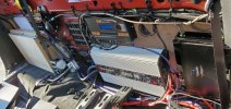
Here's a not particularly great photo of the grounding point. Right now, it's just the lugs from the wires there, but I will add a flat washer and a toothed washer to ensure a strong hold, and add a bit of blue Loc Tite to the bolt threads. I'll also re-paint the frame not covered by the lugs and washer.

Incidentally, if you're tapping a hole for an M8 bolt, a 7mm drill bit is ideal. That's about 9/32 inch. I have 1/4" drill bits, and I have 5/16" drill bits. The latter would be too big, so I went with 1/4". I can tell you, tapping a 1/4" hole with an M8 tap isn't easy, but it worked! Though I might have shortened the life of my tap a bit.

Again, I'm calling this a success, and I appreciate everyone's input.

tempImageS9o50m.jpg
 
I'd love to hear more about how you did that. What are you doing to bring the power outside the cab (to the bed, etc.)?

My preference would be to keep the batteries in the cab, so they're better shielded from extreme temperatures (both high and low). I park my truck in my driveway. I've got wireless, data logging thermometers in the cab and in the bed, and in August, the highest temperature in the cab was 103.5° F, versus 117.5° in the bed. (The bed is covered; if I open it, the temperature drops dramatically).

I'd also need to bring power, from solar, back to the battery. If I knew a clean way to run wire from the cab to the bed, I would have gone that route instead.
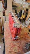
This is how i assembled the Headway cells so they fit where the factory subwoofer used to be, they have way more capacity and last way longer than any AGM battery, they also cost more to build but it's worth it, i run over 8000 watts on the sound system and not much voltage drop, i have built a few different cell packs for friends they range from $400 to $600
I run a 1/0-gauge wire through the firewall and under the trim to behind the seats but under the seats under the carpet there are some holes plugged with rubber caps that lead to the cross frame of the chassis that's the easier way to get a power wire out of the cab to the bed but you have to drill a hole in the cab to get a decent sise wire in there.
 

Attachments

  • FB_IMG_1614391137154.jpg
    FB_IMG_1614391137154.jpg
    154 KB · Views: 22
  • 20211204_133040.jpg
    20211204_133040.jpg
    141 KB · Views: 22

Users who are viewing this thread

Back
Top