5thGenRams Forums

Register a free account today to become a member! Once signed in, you'll be able to participate on this site by adding your own topics and posts, as well as connect with other members through your own private inbox!

eTorque Bearing Replacement, Fixed Grinding Noise

Joined
Feb 3, 2025
Messages
11
Reaction score
12
Points
3
Age
37
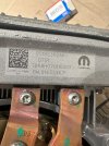
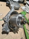
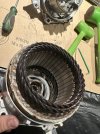
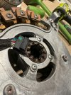
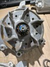
Like many others with the 5.7 eTorque mine started making a grinding noise. At first it sounded like an old power steering pump without fluid. Then, it progressed into a horrible bad bearing sound. All the while the dealer told me the part was backordered and that I should keep driving it (my truck is under warranty with about 25000 miles on it). Eventually the noise got so bad I told the dealer I couldn't drive it any longer as I was worried about causing other damage or short circuiting and starting a fire. Again, they nor Ram offered any solution so I took matters into my own hands. In the next few posts I will try to spell out how to remove and rebuild the eTorque unit (provided yours failed the same as mine). My truck is a '21. I have no idea if they are all the same. I also have no idea if my repair procedure will cause other damage of any other kind. The risk to attempt repair is yours. This probably voids warranty. My repair was successful and my truck runs fine with no abnormal noises. I apologize ahead of time as the following posts will likely be long. I will try to get them typed up and posted tonight or tomorrow. I joined the forum to hopefully help others that are stuck in the same crappy situation.
 
eTorque MGu removal, 5.7hemi. There are some youtube videos that show this pretty well.
1. Most instructions say to disconnect the 12V battery lead. I did not. Up to you to risk this or not. Treat all connections as if they are LIVE.
2. There are 2 belt tensioners on the MGU belt system. One is a standard rotary style tensioner positioned clockwise under the MGU. This tensioner can be locked out with a pin or allen wrench when it is fully rotated out of the way. This one is easy. The 2nd tensioner is kind of counter clockwise to the left of the MGU and it is mounted down low. It is a straight line style hydraulic tensioner. It is a pain to release in single digit weather hopefully for those of you in a warmer climate it is easier. There is a half inch drive square hole directly under the idler pulley. I recommend a second set of hands to hold the tensioner out of the way while the belt is removed. It can be done solo (I did) but it sucks.
3. Remove the belt once tension is off. This is still not much fun in the cold (belt shrinkage maybe). In my case, I loosened the MGU mounting bolts to give a little bit more slack in the belt to remove it.
4. With the belt off I went after the electrical connections. There is a harness on the top passenger side of the MGU electronics module. This has a little clip the is pulled towards the passenger side to release the lock. This is a tricky harness, but be patient and it will unclip. Then undo the 48V main power cable on the driver side of the module. Use a fine blade screwdriver to pop the cover open on this connection. Then I believe it was a 10mm bolt to release the terminal off the stud. I have every reason to believe this connection is LIVE. DO NOT touch any grounded metal points while working on this terminal. Make sure this 48V wire is put off to the side in a way that cannot short out.
5. There are 5 bolts that hold the MGU on (pretty sure its five lol). 4 on the front and one on the divers side. That 5th bolt on the drivers side is not much fun due to the fuel injection wire harness guide in the way. I snipped the zip tie holding that harness in place to get a little more play to sneak a socket under.
6. With all wires, belt, and bolts removed the MGU can be removed. Mine needed a little persuasion with a dead blow hammer. Just light taps to loosen it side to side. Be careful, it and the module can be damaged. Once removed you will see the two main bolts (long ones) go into a couple nuts that are captured but allowed to move. These pinch the bracket thus requiring the dead blow. I recommend that after removal you thread the bolts back into these nuts and give each a good hit with a hammer to drive that nut out very slightly. This will make install easier because you will have a bit of clearance. They tighten back up when you torque down the bolts on reinstall.
 
Once the MGU is removed, you need to get the electronics module off the top of the MGU.
1. There is a black plastic cover on the rear of the MGU. 4 small torx bolts hold the cover on. Remove them and the cover.
2. You will see 3 large copper bus bar connections to the electronic module. Remove the bolts from these connections. The copper bus bars are not as rigid as they appear. They are not solid copper but rather laminated from thin pieces of copper. For these reason I remove the bolts at the module side, not the motor generator side. Treat them gently.
3. To the left of the main copper bus bars is a small round connector. Not sure what the trick is to remove this but I did snap one of the clips taking this apart. Be gentle, and hopefully have better luck than me.
4. Further left on the side of the MGU is one further bus bar connection (grounding strap I think). It is silver colored but the same delicate copper lamination. Remove the bolt from this as well.
5. There are 4 bolts that hold the module to the motor generator. There are also 4 standoffs that hold the module up. The stand offs will fall out when the module bolts are removed. Don't loose these.
6. Now the module should be able to be lifted free of the motor generator.

Take care not to damage those copper bus bar connections.
 

Attachments

  • IMG_3496.jpg
    IMG_3496.jpg
    221.5 KB · Views: 13
Now the fun part, split the cases.
1. There are 4 long torx bolts that hold the case together. Also, there are no "keys" that align the two halves of the cases together. I highly recommend that you carefully mark both halves before splitting them. Remove the four long bolts.
2. To split the cases without a press I used a dead blow and alternated blows around the front of the case. I focused blows on the heavy sections of casting that stick out where the main mounting bolt pads are cast in. Alternate from side to side working the cases apart. A shop press would probably work better but I didn't have access to one.
 

Attachments

  • IMG_3488.jpg
    IMG_3488.jpg
    201.1 KB · Views: 10
  • IMG_3490.jpg
    IMG_3490.jpg
    195.1 KB · Views: 10
Last edited:
Now that the cases are split we see the issue. The rear bearing is shot.
3. Behind that rear bearing is a resolver of some kind (my guess is it reports shaft position/rpm to the controller). It needs to be removed to get the bearing off. It is a single nut that is easily removed with a small impact driver. The reluctor wheel is keyed and just slides off the shaft. Mark it for which side goes on the shaft first. If you forget, look at the witness marks on the shaft and reluctor.
4. Pull the bearing off the shaft (if yours is on the shaft) with a small bearing puller. Two open end wrenches used 180 degrees off from each other would work also. My bearing was not too tight on the shaft. If your bearing stayed in the housing you will need to remove the resolver from the rear of the case and press the bearing out that way using a drift or deep socket. Looks like 3 small allen bolts to remove the sensor. I would mark it for orientation before removal.

One thing I would note is that if you look close at these pictures the resolver sensor and reluctor wheel are damaged. I imagine this damage was from the bad bearing allowing the shaft to orbit excessively causing contact. In this case, the system still functions fine. Your damage may be beyond this point. You won't know until inspection. I doubt this is an easily purchased part. Also, my truck will throw a code when I wash it. My guess is water gets in the windings of this sensor due to the damage. Code clears on it's own when everything dries.
 

Attachments

  • IMG_3489.jpg
    IMG_3489.jpg
    211 KB · Views: 11
  • IMG_3493.jpg
    IMG_3493.jpg
    176.5 KB · Views: 11
Excellent write up. Hope I never need the information, but as the eTorque MGU gets older this is gonna be more common to repair a bearing that goes bad.
Where did you get the bearing part number? Parts book or off of the bearing?
 
In my unit the bad bearing was an SKF 6003 double sealed bearing. I was not able to read the bearing part number due to corrosion but I measured the shaft at 17mm, bearing OD at 35mm, and thickness at 10mm. This is a 6003 size bearing and it is double sealed. I have no idea what precision level bearing was installed from the factory. I went with a 6003-2RS double sealed bearing in ABEC 3 precision level. The bearing was in stock at McMaster Carr and I had it next day. McMaster Carr part number 6661K86. Cost about $40 without shipping.

Re-assembly is pretty much the reverse of the above steps.

1. Press new bearing onto shaft.
2. Install reluctor wheel back onto shaft and secure with nut. Install the resolver sensor if you removed it.
3. Very carefully start putting the case halves back together. Take care to line up the marks you made earlier.
4. I started the long torx bolts back into their threads once I was happy with alignment. Keeping an eye on the gap around the halves, start snugging up the long torx bolts in a star pattern. Take your time to bring the halves back together evenly. Once everything seemed tight, I tightened up the torx bolts. I have no idea what torque is needed, I just went until it felt correct.
5. Re-install the electronic module onto the motor generator using the reverse of the above steps. Keep everything loose until you get all 4 stand offs back in place and the bolts through them. This was a bit tricky, but not too bad.
6. Snug up and then tighten the 4 bolts holding the module on before fully tightening the electrical connections.
7. Plug in the small round electrical connector.
8. Re-install the black plastic cover. Mine had debris in it from the resolver damage so I cleaned it before putting it back on. Go easy on those little screws. I did not crack the cover but it seemed like it would be easy to do.

At this point the motor generator should be reassembled and ready to put back in the truck. Give it a spin. It should spin nice and smooth. There are no brushes or commutator so it should not have anything dragging or grinding. Just normal friction from bearing grease and seals dragging.
 
Install back in the truck is reverse of removal. Again, I do not know what torque requirements are for the bolts. I went by feel. 4 bolts on the front of the MGU and one on the drivers side. Then connect the 48V connection, take caution as it is LIVE, followed by connecting the harness on the passenger side.

Reinstall the belt and unpin the rotary belt tensioner to release it back onto the belt. Check belt routing and alignment and you should be good. Probably make sure you have no extra parts or bolts laying around.

When I fired my truck up after rebuilding the MGU it was as if I never removed it. No lights and no more grinding noises. Everything functions as normal, but I have been disabling the auto start/stop out of caution. System is showing normal voltage and charging fine. As I mentioned above, there was damage in my MGU from the failed bearing so I do intend to have it replaced under warranty when/if parts ever arrive.

I hope this info is helpful to those of you in the same boat. If you have questions let me know and I will do my best to answer. Thanks.
 
Excellent write up. Hope I never need the information, but as the eTorque MGU gets older this is gonna be more common to repair a bearing that goes bad.
Where did you get the bearing part number? Parts book or off of the bearing?
The bearing was too corroded to read. So I used a micrometer and bore mic to measure the shaft, bore, and thickness. Then cross referenced it to the industry standard size. It is a very common size bearing.
 

Users who are viewing this thread

Back
Top