5thGenRams Forums

Register a free account today to become a member! Once signed in, you'll be able to participate on this site by adding your own topics and posts, as well as connect with other members through your own private inbox!

Adding blindspot rear view (and Passenger side dimming) mirror glass

so these i know nothing about. i didn't add or change any switches in the cab related to this mod, so maybe someone else can chime in here if they have. that is also a much newer panel than mine is as the switches are completely different. sorry i can't help with that part of it!
The blank switch should be used to adjust the air suspension ride height.
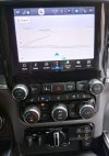
I did buy 68447098AB (shown in the 2nd picture, above) and transplanted the circuit board and switches into my panel. Tedious; but not difficult. Lots of sring clips to remove simutaneously. Fortunately didn't break anything. Picture is my panel with the ParkSense switches transplanted in.
 

Attachments

  • Center stack with ParkSense switches.jpg
    Center stack with ParkSense switches.jpg
    123.2 KB · Views: 11
So now what I need to do, is if possibly find a way to get the connectors and pins for the blind spot led connector. I’d like to do this all with factory connectors if I can, but some things just aren’t findable sometimes. I just like that they are small and snap into the back of the mirror glass and won't be bounding around in there. (otherwise i'll have to do it with some generic connectors, or just solder them all - which i'd like to avoid.)

This is the connector on the mirror glass for blind spot:
View attachment 144575

Recently got some help from @JayStein, And I now know this is what the mating connector looks like.
View attachment 144576

And it’s listed with this part number as a repair kit that doesn’t exist anywheres:
View attachment 144577

So I'm wondering if @Jimmy07 or anyone has a molex part number for this connector... or a way to find it with this... I'm not entirely sure how to obtain that info with this info haha.

This is a great writeup. And, I really appreciate your research. I'm stuck here. I cannot identify Pin 1 and Pin 2 on this connector. Even using the datasheet; I'm not confident which is which. Also the leads on the new mirror don't correspond to any of the color combinations on the DCCTools diagrams. How did you differentiate 1 for 2? Thanks, Brent
 

Users who are viewing this thread

Members online

Back
Top